

颜色传感器DIY图解
电子说
描述
第1步:BoM
Arduino
RGB LED
光敏电阻
10kΩ电阻
3x100Ω电阻器
跳线
面包板电线
步骤2:连接RGB LED
这将是我们电路的发射器部分发出不同的颜色,这些颜色将从物体反弹,通过光学定律将被检测到我们的光传感器。
*将引脚2,最长引脚连接到Arduino上的GND引脚。
*连接引脚1, R GB的红色LED LED指向Arduino上的引脚5。
*将引脚3,R G B LED的贪婪色LED连接到Arduino上的引脚6。
*将引脚4,RG B LED的蓝色LED连接到Arduino上的引脚9。
您会注意到所有这些都插入标有tilda符号“〜”的PWM引脚,这样我们就可以独立控制每个LED的亮度。
步骤3:连接光电传感器
来自发射器(RGB)LED的反射光从中弹回光传感器将读取任何物体,光电传感器将使用校准值来找到特定颜色的各个RGB颜色值。
确保将光传感器移近发射器。
*将其中一个引脚(称为光纤传感器的引脚1)连接到Arduino上的GND引脚
*将光电传感器的引脚2连接到上面的3.3V引脚Arduino的。
*将光电传感器的引脚2连接到Arduino上的A0引脚。
你会注意到最后两条接线都是平行的。这是因为我们正在制作一个分压器,以便在反射光强度发生变化时获得变化的电压读数。
步骤4:代码
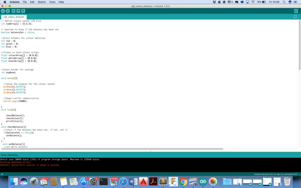


// Define colour sensor LED pins int ledArray[] = {5,6,9}; // boolean to know if the balance has been set
boolean balanceSet = false; //place holders for colour detected
int red = 0;
int green = 0;
int blue = 0; //floats to hold colour arrays
float colourArray[] = {0,0,0};
float whiteArray[] = {0,0,0};
float blackArray[] = {0,0,0}; //place holder for average
int avgRead; void setup(){
//setup the outputs for the colour sensor
pinMode(2,OUTPUT);
pinMode(3,OUTPUT);
pinMode(4,OUTPUT);
//begin serial communication
Serial.begin(9600); }
void loop(){ checkBalance();
checkColour();
printColour();
}
void checkBalance(){
//check if the balance has been set, if not, set it
if(balanceSet == false){
setBalance();
}
}
void setBalance(){
//set white balance
delay(5000); //delay for five seconds, this gives us time to get a white sample in front of our sensor
//scan the white sample.
//go through each light, get a reading, set the base reading for each colour red, green, and blue to the white array
for(int i = 0;i《=2;i++){
digitalWrite(ledArray[i],HIGH);
delay(100);
getReading(5); //number is the number of scans to take for average, this whole function is redundant, one reading works just as well.
whiteArray[i] = avgRead;
digitalWrite(ledArray[i],LOW);
delay(100);
}
//done scanning white, now it will pulse blue to tell you that it is time for the black (or grey) sample.
//set black balance
delay(5000); //wait for five seconds so we can position our black sample
//go ahead and scan, sets the colour values for red, green, and blue when exposed to black
for(int i = 0;i《=2;i++){
digitalWrite(ledArray[i],HIGH);
delay(100);
getReading(5);
blackArray[i] = avgRead;
//blackArray[i] = analogRead(2);
digitalWrite(ledArray[i],LOW);
delay(100);
}
//set boolean value so we know that balance is set
balanceSet = true;
delay(5000); //delay another 5 seconds to let us catch up
} void checkColour(){
for(int i = 0;i《=2;i++){
digitalWrite(ledArray[i],HIGH); //turn or the LED, red, green or blue depending which iteration
delay(100); //delay to allow CdS to stabalize, they are slow
getReading(5); //take a reading however many times
colourArray[i] = avgRead; //set the current colour in the array to the average reading
float greyDiff = whiteArray[i] - blackArray[i]; //the highest possible return minus the lowest returns the area for values in between
colourArray[i] = (colourArray[i] - blackArray[i])/(greyDiff)*255; //the reading returned minus the lowest value divided by the possible range multiplied by 255 will give us a value roughly between 0-255 representing the value for the current reflectivity(for the colour it is exposed to) of what is being scanned
digitalWrite(ledArray[i],LOW); //turn off the current LED
delay(100);
}
}
void getReading(int times){
int reading;
int tally=0;
//take the reading however many times was requested and add them up
for(int i = 0;i 《 times;i++){
reading = analogRead(0);
tally = reading + tally;
delay(10);
}
//calculate the average and set it
avgRead = (tally)/times;
}
//prints the colour in the colour array, in the next step, we will send this to processing to see how good the sensor works.
void printColour(){
Serial.print(“R = ”);
Serial.println(int(colourArray[0]));
Serial.print(“G = ”);
Serial.println(int(colourArray[1]));
Serial.print(“B = ”);
Serial.println(int(colourArray[2]));
//delay(2000);
}
步骤5:校准
首先准备一张黑白纸上传代码。
上传代码后,您会注意到在程序运行的前5秒内,RGB LED会发出各种颜色。在前5秒钟,在LED和光电传感器上放置一张黑纸。然后在接下来的5秒钟内将纸张切换到白纸上。
编写代码,使前10秒为校准周期。
第6步:测试并享受!
取出不同颜色的纸张并进行测试。它会将各个R,G,B值打印到屏幕上。
- 相关推荐
- 颜色传感器
-
传感器应用技术:TCS3200颜色传感器的应用#传感器学习电子 2022-11-08
-
传感器应用技术:颜色传感器原理与分类#传感器学习电子 2022-11-08
-
传感器应用技术:颜色传感器的硬件设计#传感器学习电子 2022-11-08
-
工业颜色识别传感器的设计2013-11-12 0
-
如何选择颜色传感器2016-01-31 0
-
颜色传感器2017-03-24 0
-
DIY图像传感器2022-08-26 0
-
霍尔式传感器图解2009-12-02 5024
-
什么是颜色传感器它有哪些类型的2020-03-27 7212
-
全色域颜色传感器分辨多颜色的传感器2020-05-13 3379
-
颜色传感器的原理及分类2020-08-02 6631
-
颜色传感器的类型有哪些 如何选择颜色传感器2022-06-21 6742
-
什么是光谱?光谱传感器相较颜色传感器优势在哪?2023-02-15 1252
-
颜色传感器的原理2023-06-30 2075
-
颜色传感器如何分辨不同颜色的糖果2021-11-17 1266
全部0条评论

快来发表一下你的评论吧 !
