

如何制作Arduino雷达
电子说
描述
第1步:材料和程序
此构建所需的材料包括:
- 1个伺服
- 1个超声波传感器
- 1个蜂鸣器
- 1面包板
- 1 UNO R3 Arduino
- 电线堆
制作此雷达所需的程序:
- Arduino IDE
- 处理3.4
要将上述程序下载到您的计算机上,请点击以下链接:
- https://www.arduino.cc/en/main/software
-https://processing.org/download/
第2步:Arduino代码
这是arduino代码,它基本上控制伺服和传感器的运动和输入。这是从youtube视频https://www.youtube.com/watch?v=JvmIutmQd9U复制而来,似乎与我的arduino板和计算机很好地配合。
// Includes the servo library
#include 。
// Defines Trig and Echo pins of the Ultrasonic Sensor
const int trigPin = 10;
const int echoPin = 11;
#define buzzerPin A0 //Defines the pin A0 as an output to buzzerPin
// Variables for the duration and the distance
long duration;
int distance;
Servo myServo; // Creates a servo object for controlling the servo motor
void setup() {
pinMode(trigPin, OUTPUT); // Sets the trigPin as an Output
pinMode(echoPin, INPUT); // Sets the echoPin as an Input
Serial.begin(9600);
myServo.attach(12); // Defines on which pin is the servo motor attached
}
void loop() {
// rotates the servo motor from 15 to 165 degrees
for(int i=15;i《=165;i++){
myServo.write(i);
delay(30);
distance = calculateDistance();// Calls a function for calculating the distance measured by the Ultrasonic sensor for each degree
Serial.print(i); // Sends the current degree into the Serial Port
Serial.print(“,”); // Sends addition character right next to the previous value needed later in the Processing IDE for indexing
Serial.print(distance); // Sends the distance value into the Serial Port
Serial.print(“。”); // Sends addition character right next to the previous value needed later in the Processing IDE for indexing
tone(buzzerPin, 10000 / distance);
}
// Repeats the previous lines from 165 to 15 degrees
for(int i=165;i》15;i--){
myServo.write(i);
delay(30);
distance = calculateDistance();
Serial.print(i);
Serial.print(“,”);
Serial.print(distance);
Serial.print(“。”);
tone(buzzerPin, 10000 / distance); //Produces a different tone according to the distance the object is from the sensor
}
}
// Function for calculating the distance measured by the Ultrasonic sensor
int calculateDistance(){
digitalWrite(trigPin, LOW);
delayMicroseconds(2);
// Sets the trigPin on HIGH state for 10 micro seconds
digitalWrite(trigPin, HIGH);
delayMicroseconds(10);
digitalWrite(trigPin, LOW);
duration = pulseIn(echoPin, HIGH); // Reads the echoPin, returns the sound wave travel time in microseconds
distance= duration*0.034/2;
return distance;
}
步骤3:处理代码
以下是我用于处理程序从超声波传感器获取信息的代码,并将其转换为它创建的显示。这是我从视频https://www.youtube.com/watch?v=JvmIutmQd9U复制的代码,该代码效果非常好,只需要进行一些调整。
p.p1 {margin: 0.0px 0.0px 0.0px 0.0px; font: 11.0px ‘Helvetica Neue’; color: #000000; -webkit-text-stroke: #000000}
p.p2 {margin: 0.0px 0.0px 0.0px 0.0px; font: 11.0px ‘Helvetica Neue’; color: #000000; -webkit-text-stroke: #000000; min-height: 12.0px}
span.s1 {font-kerning: none}
import processing.serial.*; // imports library for serial communication
import java.awt.event.KeyEvent; // imports library for reading the data from the serial port
import java.io.IOException;
Serial myPort; // defines Object Serial
// defubes variables
String angle=“”;
String distance=“”;
String data=“”;
String noObject;
float pixsDistance;
int iAngle, iDistance;
int index1=0;
int index2=0;
PFont orcFont;
void setup() {
size (1200, 700); // ***CHANGE THIS TO YOUR SCREEN RESOLUTION***
smooth();
myPort = new Serial(this,“/dev/cu.usbmodem143401”, 9600); // starts the serial communication
myPort.bufferUntil(‘。’); // reads the data from the serial port up to the character ‘。’. So actually it reads this: angle,distance.
}
void draw() {
fill(98,245,31);
// simulating motion blur and slow fade of the moving line
noStroke();
fill(0,4);
rect(0, 0, width, height-height*0.065);
fill(98,245,31); // green color
// calls the functions for drawing the radar
drawRadar();
drawLine();
drawObject();
drawText();
}
void serialEvent (Serial myPort) { // starts reading data from the Serial Port
// reads the data from the Serial Port up to the character ‘。’ and puts it into the String variable “data”。
data = myPort.readStringUntil(‘。’);
data = data.substring(0,data.length()-1);
index1 = data.indexOf(“,”); // find the character ‘,’ and puts it into the variable “index1”
angle= data.substring(0, index1); // read the data from position “0” to position of the variable index1 or thats the value of the angle the Arduino Board sent into the Serial Port
distance= data.substring(index1+1, data.length()); // read the data from position “index1” to the end of the data pr thats the value of the distance
// converts the String variables into Integer
iAngle = int(angle);
iDistance = int(distance);
}
void drawRadar() {
pushMatrix();
translate(width/2,height-height*0.074); // moves the starting coordinats to new location
noFill();
strokeWeight(2);
stroke(98,245,31);
// draws the arc lines
arc(0,0,(width-width*0.0625),(width-width*0.0625),PI,TWO_PI);
arc(0,0,(width-width*0.27),(width-width*0.27),PI,TWO_PI);
arc(0,0,(width-width*0.479),(width-width*0.479),PI,TWO_PI);
arc(0,0,(width-width*0.687),(width-width*0.687),PI,TWO_PI);
// draws the angle lines
line(-width/2,0,width/2,0);
line(0,0,(-width/2)*cos(radians(30)),(-width/2)*sin(radians(30)));
line(0,0,(-width/2)*cos(radians(60)),(-width/2)*sin(radians(60)));
line(0,0,(-width/2)*cos(radians(90)),(-width/2)*sin(radians(90)));
line(0,0,(-width/2)*cos(radians(120)),(-width/2)*sin(radians(120)));
line(0,0,(-width/2)*cos(radians(150)),(-width/2)*sin(radians(150)));
line((-width/2)*cos(radians(30)),0,width/2,0);
popMatrix();
}
void drawObject() {
pushMatrix();
translate(width/2,height-height*0.074); // moves the starting coordinats to new location
strokeWeight(9);
stroke(255,10,10); // red color
pixsDistance = iDistance*((height-height*0.1666)*0.025); // covers the distance from the sensor from cm to pixels
// limiting the range to 40 cms
if(iDistance《40){
// draws the object according to the angle and the distance
line(pixsDistance*cos(radians(iAngle)),-pixsDistance*sin(radians(iAngle)),(width-width*0.505)*cos(radians(iAngle)),-(width-width*0.505)*sin(radians(iAngle)));
}
popMatrix();
}
void drawLine() {
pushMatrix();
strokeWeight(9);
stroke(30,250,60);
translate(width/2,height-height*0.074); // moves the starting coordinats to new location
line(0,0,(height-height*0.12)*cos(radians(iAngle)),-(height-height*0.12)*sin(radians(iAngle))); // draws the line according to the angle
popMatrix();
}
void drawText() { // draws the texts on the screen
pushMatrix();
if(iDistance》40) {
noObject = “Out of Range”;
}
else {
noObject = “In Range”;
}
fill(0,0,0);
noStroke();
rect(0, height-height*0.0648, width, height);
fill(98,245,31);
textSize(25);
text(“10cm”,width-width*0.3854,height-height*0.0833);
text(“20cm”,width-width*0.281,height-height*0.0833);
text(“30cm”,width-width*0.177,height-height*0.0833);
text(“40cm”,width-width*0.0729,height-height*0.0833);
textSize(40);
text(“Ryan‘s Radar”, width-width*0.875, height-height*0.0277);
text(“Angle: ” + iAngle +“ °”, width-width*0.48, height-height*0.0277);
text(“Distance: ”, width-width*0.26, height-height*0.0277);
if(iDistance《40) {
text(“ ” + iDistance +“ cm”, width-width*0.225, height-height*0.0277);
}
textSize(25);
fill(98,245,60);
translate((width-width*0.4994)+width/2*cos(radians(30)),(height-height*0.0907)-width/2*sin(radians(30)));
rotate(-radians(-60));
text(“30°”,0,0);
resetMatrix();
translate((width-width*0.503)+width/2*cos(radians(60)),(height-height*0.0888)-width/2*sin(radians(60)));
rotate(-radians(-30));
text(“60°”,0,0);
resetMatrix();
translate((width-width*0.507)+width/2*cos(radians(90)),(height-height*0.0833)-width/2*sin(radians(90)));
rotate(radians(0));
text(“90°”,0,0);
resetMatrix();
translate(width-width*0.513+width/2*cos(radians(120)),(height-height*0.07129)-width/2*sin(radians(120)));
rotate(radians(-30));
text(“120°”,0,0);
resetMatrix();
translate((width-width*0.5104)+width/2*cos(radians(150)),(height-height*0.0574)-width/2*sin(radians(150)));
rotate(radians(-60));
text(“150°”,0,0);
popMatrix();
}
步骤4:超声波传感器支架
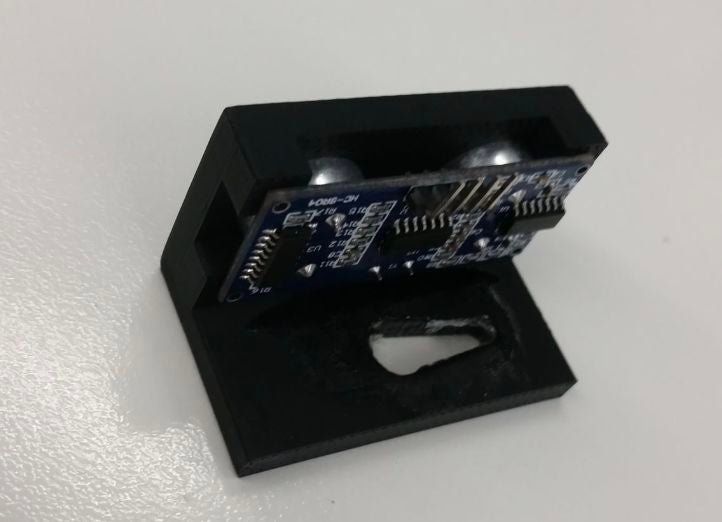
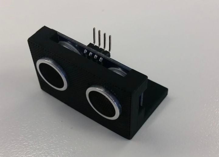
由于我对此项目的启发并未包含任何类型的支架来固定超声波传感器在适当的位置,我决定3D打印这个支架是一个好主意,让完成的设计看起来更整洁,并使一切更容易组合。保持超声波传感器的部分最终相对紧密地安装在超声波传感器周围,在保持其就位方面做得很好。然而,在下面切出的用于伺服臂进入的孔有点太大,所以我需要添加很多胶水来保持它的位置。但总的来说,它的效果非常好,并且设计看起来很漂亮。
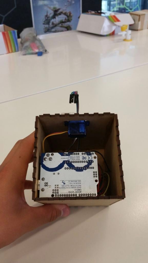
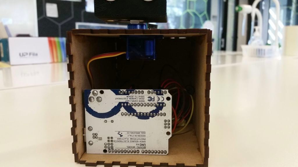
第5步:激光切割盒设计
实施此框以使项目具有干净和专业的外观。它在隐藏所有电线和arduino板本身方面做得很好。为了创建实际的盒子设计,我使用网站http://www.makercase.com/来获得手指边缘以将盒子的每一侧连接在一起。这是一个非常有用的网站,因为它节省了我大量的时间,并且非常容易使用。从雷达的成品中可以看出,我在设计的侧面和顶部切出了测量孔,以便允许项目的部分需要在外面。这包括用于伺服的孔,我从下面粘到盒子上,连接到超声波传感器,蜂鸣器,以及从计算机到arduino板本身。这是相当大的(盒子里有很多空间),但至少它给你很大的工作空间,没有任何东西是狭窄的。如果你自己做一个盒子设计,你肯定可以做得更小,一切都会适合。
步骤6:接线构造
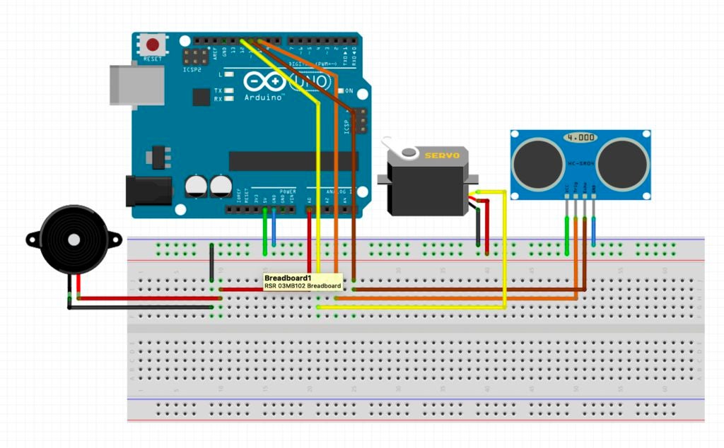
根据arduino代码,超声波传感器必须连接到引脚10 11.虽然和所有超声波传感器一样,它也必须连接到地和5V引脚。伺服必须连接到引脚12(myServo.attach(12);),它还必须连接到地和5V引脚。至于蜂鸣器,它只接地和模拟输出引脚A0。一旦你为雷达附加了所有必要的物品,你的电路应该看起来有点像上图。此外,尽量保持一切整洁!一旦电路在盒子里,电线都非常缠结,有可能一根或两根电线滑出不到位置并导致雷达发生故障。它发生在我身上,我发现它从那时起就保持整洁,减少了这些事件的发生。
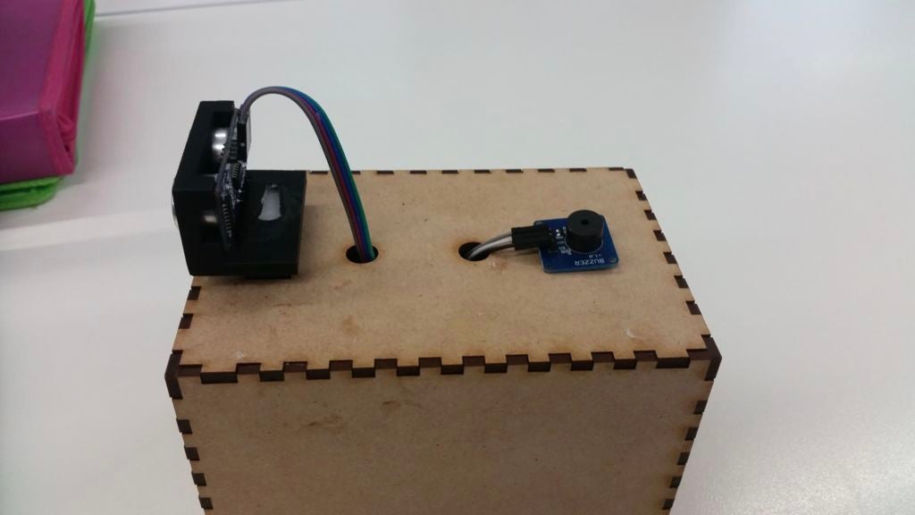
步骤7:组装
使用强力超级胶水组装激光切割盒,因此完成后不会有碎片分开雷达。我发现更容易使用一些书来支撑盒子的一侧,这样我就可以粘上相邻的一面。在那里拿着它约5分钟后,我会继续到下一侧,依此类推。记住不要粘上其中一端,因为你显然需要放入并取出雷达。一旦盒子上的胶水硬化,您就可以继续装配。首先,我将蜂鸣器粘在外壳的顶部(如上图所示),然后当它干燥时,我将电线穿过相对的孔并将它们连接到蜂鸣器上。当谈到伺服系统时,我将伺服的小翼粘在盒子下面,所以只有伺服的顶部显示出来。这使得整个产品看起来既美观又保持其实用性,伺服头可随时轻松访问。然后使用3D打印支架中的超声波传感器,使用胶水将支架连接到伺服系统,以确保其安全。完成后,您的项目即可进行测试!
步骤8:执行
首先将计算机连接到arduino板。接下来,打开两个程序。加载arduino代码后,将其上传到主板。这应该开始伺服和蜂鸣器,因此会产生噪音,伺服也会相应转动。然后,当加载处理代码时,单击运行,如果一切顺利运行,则应显示雷达的动画。如果没有发生这种情况,请检查您使用的端口名称是否与代码中的名称完全相同。例如,如果我使用端口“/dev/cu.usbmodem143401”,请确保处理中的代码行显示“myPort = new Serial(this,”/dev/cu.usbmodem143401“,9600);”。这应该解决所有问题,它应该运行顺利。启动和运行的过程都可以在上面的视频链接上看到它正在工作和检测对象。
-
arduino雷达制作教程硬创客 2021-08-24
-
TF系列激光雷达在Arduino上的开发例程2017-11-22 0
-
开源资料基于Arduino的倒车雷达(原理图&源代码)2020-12-18 0
-
基于Arduino的触摸变色台灯制作2017-01-22 1131
-
几个Arduino创意制作分享2017-10-16 2516
-
基于Arduino的趣味电子制作2018-06-26 1952
-
Arduino教程之如何使用Arduino制作一个宝宝使用的小桔灯详细资料概述2019-01-04 997
-
用arduino制作雷达2019-04-17 10900
-
怎样制作Arduino克隆板2019-08-02 2528
-
Arduino雷达的制作教程2019-08-12 16270
-
Arduino雷达项目2022-10-31 264
-
制作基于Arduino的超声波雷达2023-02-08 517
-
Arduino:非接触式开关的制作与控制2023-02-20 1165
-
Arduino制作循迹小车教程2024-01-05 166
全部0条评论

快来发表一下你的评论吧 !
