

如何制作水族馆管理系统
电子说
描述
步骤1:组件
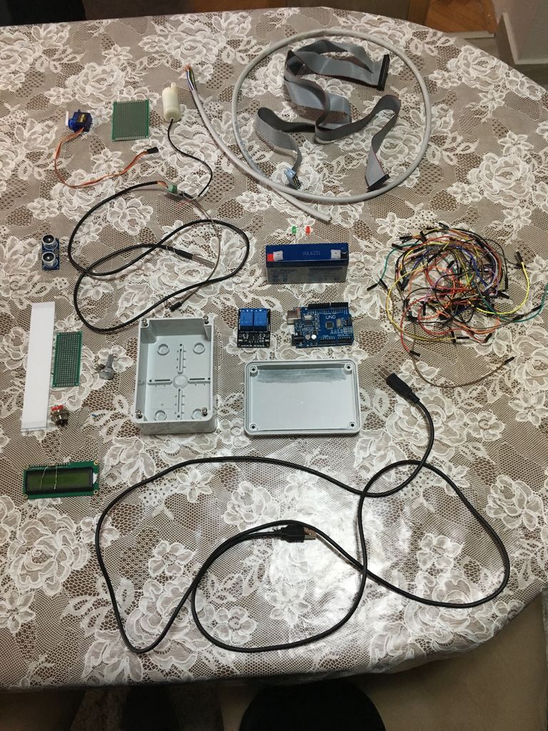
这里我们将列出该项目所需的所有组件。
Arduino Uno
超声波传感器
LCD(16x2)
电位计(10k)
伺服电机
5V 2通道继电器
水温传感器
跳线电缆
光敏电阻器
水泵水平型
1x 2.2k欧姆,1x220欧姆,1x1k欧姆,1x 4.7欧姆电阻器
6V可充电电池
有机玻璃中的4x白色LED二极管
2x Led二极管
Arduino Box
水泵软管
CSA电缆组件LL83498 AWM色带连接器
DS电缆LIYCY 8x0.5 mm2阻燃剂
RVVB 2x1.5 mm2
KCD11-101开/关开关
镁片盒
晶体管7805
水族箱
Bi g 10 Litters Water Bottle
金属盒(用于超声波,伺服)
步骤2:使用光敏电阻和开关进行盒切割和LCD安装
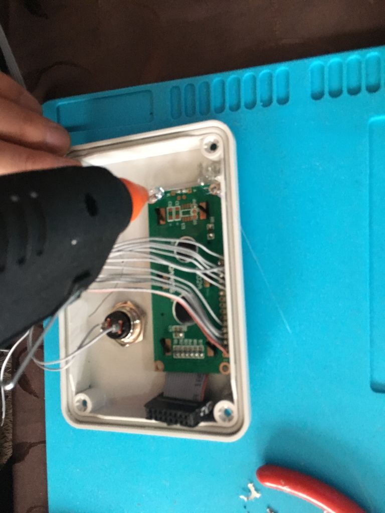
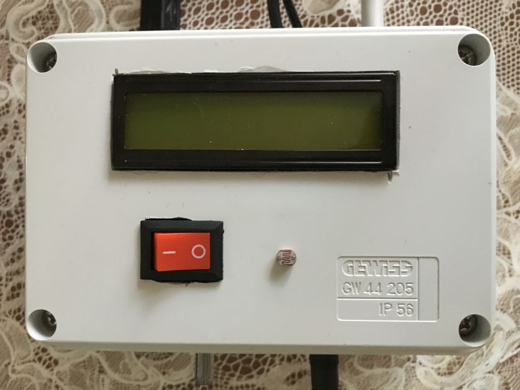
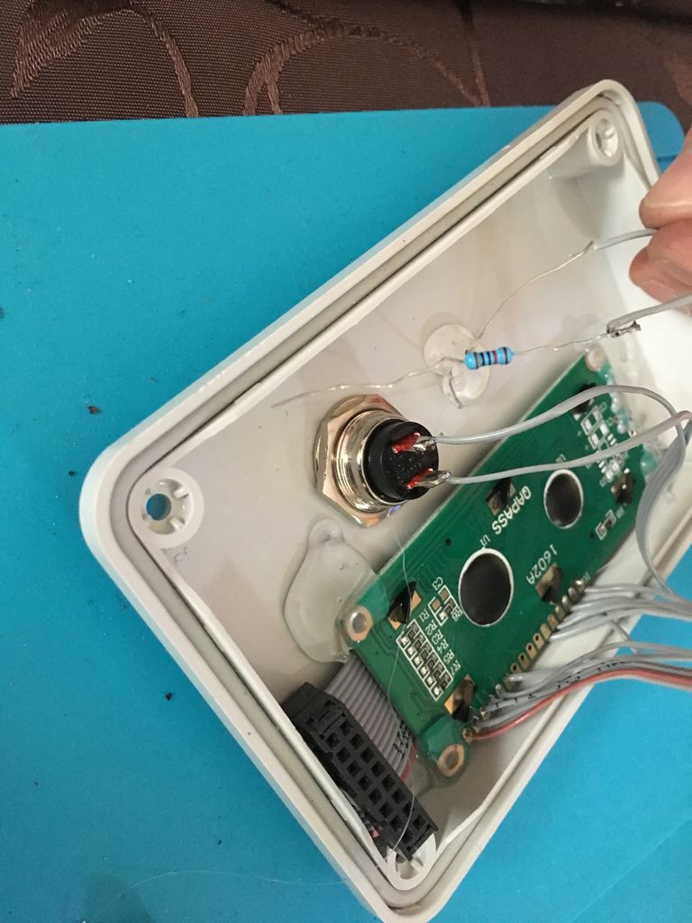
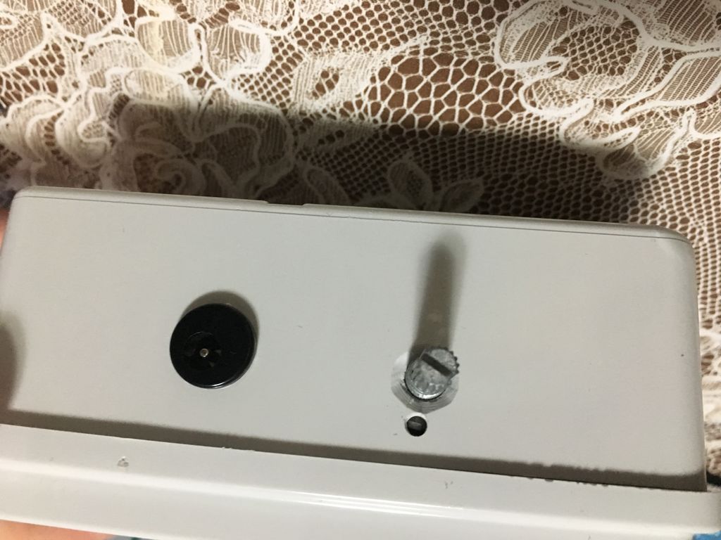
首先,我们测量LCD的长度,在我们的情况下为7x2.5厘米,因此它可以放在盒子的正面。稍后我们测量开关按钮(2x1.3 cm)和光敏电阻,我们将它们添加到盒子的正面。
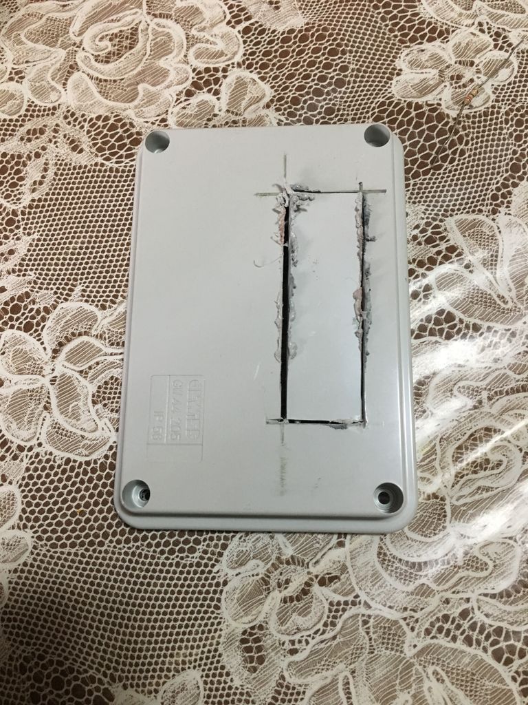
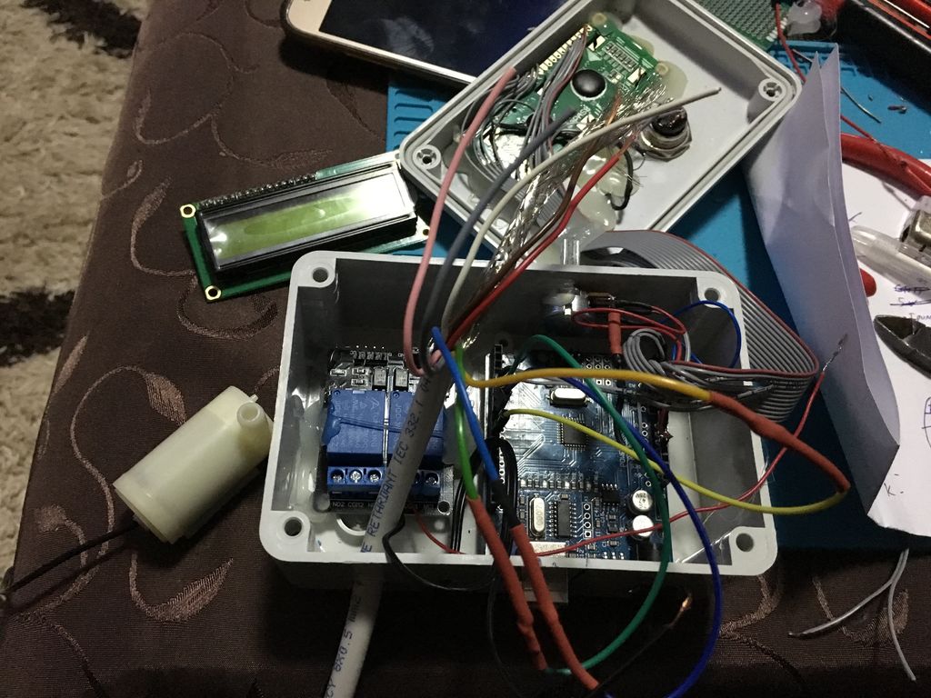
然后,在盒子的一侧,我们钻了几个孔,2个用于Arduino,1个用于水温传感器,1个用于水泵,1个用于DS电缆。这些电缆后来连接在水族箱上方的金属盒中。另一方面,我们钻了2个孔,一个用于电位器,一个用于电源。
接下来,我们从两侧切割带状连接器,如普通电线,以便将它们与Arduino连接另一边和LCD,光敏电阻和电位计在另一边。从功能区到Arduino的接线如下:
带有VSS的1-s导线,带有VSS的LCD和带Arduino的GND
带状的2-wire导线在LCD上使用VDD,在Arduino上使用VCC(5v)
带有R0的3线电缆和LCD电位器(中间引脚)
带有RS的带状线的第4根电线在Arduino上的LCD和数字引脚5上
带有LED的第5条线,LCD上的RW和Arduino上的GND
带有数字引脚4的LCD上带有E的带的第6条线在Arduino上
带有D4的7号线在LCD上带有模拟引脚2在Arduino
第8条线从带有D5的LCD上带有模拟引脚3在Arduino上
第9条导线,带有D6的LCD,带有模拟引脚4,位于Arduino
第10根导线,带有D7的LCD,带有模拟引脚5,位于Arduino上
带有A的第11条导线,带有A的LCD + 2.2k电阻,带有VCC(5v)的Arduino
第12根导线来自带状,带有K的LCD,带有GND的Arduino
带有VCC光纤的带状第13条线在Arduino上使用VCC进行电压调整
带光纤电阻器上带有GND的第14根导线,带有1.1k电阻+ GND和Arduino上的模拟引脚1(来自Arduino的GND线和引脚线与电阻器焊接在一起)与带状导线连接)
盒子前面的所有元件都用胶枪粘合。
注意:全部所有模块的VCC线焊接在Arduino上VCC引脚的一根导线上。所有模块的GND线也一样。
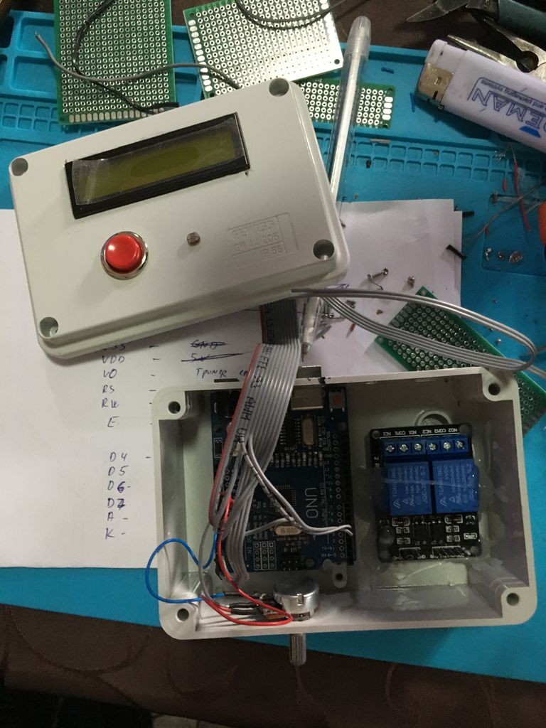
步骤3:将Arduino与继电器屏蔽,泵和LED连接
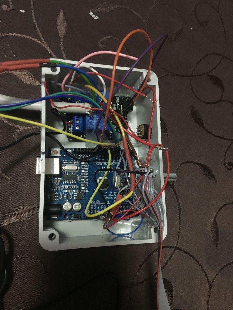
首先,我们需要将继电器与Arduino连接起来。继电器的VCC到Arduino的VCC,继电器的GND到Arduino的GND,继电器的IN1引脚,Arduino的数字引脚10和Arduino的数字2的IN2。
接下来我们要连接水泵通过开关连接到第一个继电器,并将温度信号指示灯发送到第二个继电器。
开关的第一个引脚连接到电源插孔上的VCC引脚,而另一个引脚则连接到电源插孔上。引脚连接到晶体管的输入引脚。电源插孔的GND引脚,晶体管的GND引脚和泵的GND引线焊接在一起。泵的VCC线与第一个继电器的NO引脚连接,而晶体管的输出引脚连接到继电器的COM引脚。
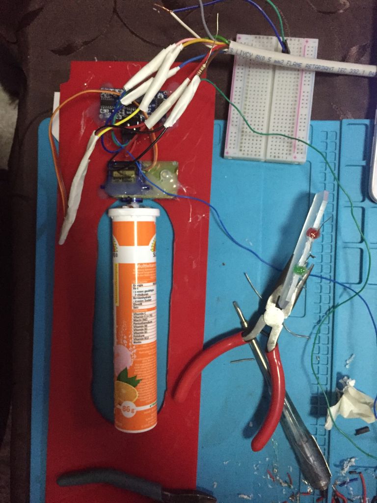
由于LED位于水族箱内部,而Arduino位于水族箱内,因此我们需要使用长线连接它们。这就是DS Cable LIYCY 8x0.5 mm2阻燃剂的用武之地。该电缆中有8根电线,因此我们将其中的2根分别与LED的阳极连接。这些导线必须连接到第二继电器,因此与绿色LED连接的导线连接在第二继电器的NC引脚上,而来自红色LED的导线与来自第二继电器的NO引脚连接。 LED阴极与220欧姆电阻和1线(GND)焊接在一起,并与Arduino的GND连接在一起。在第二个继电器上的COM引脚来自Arduino的VCC。
步骤4:连接其他传感器
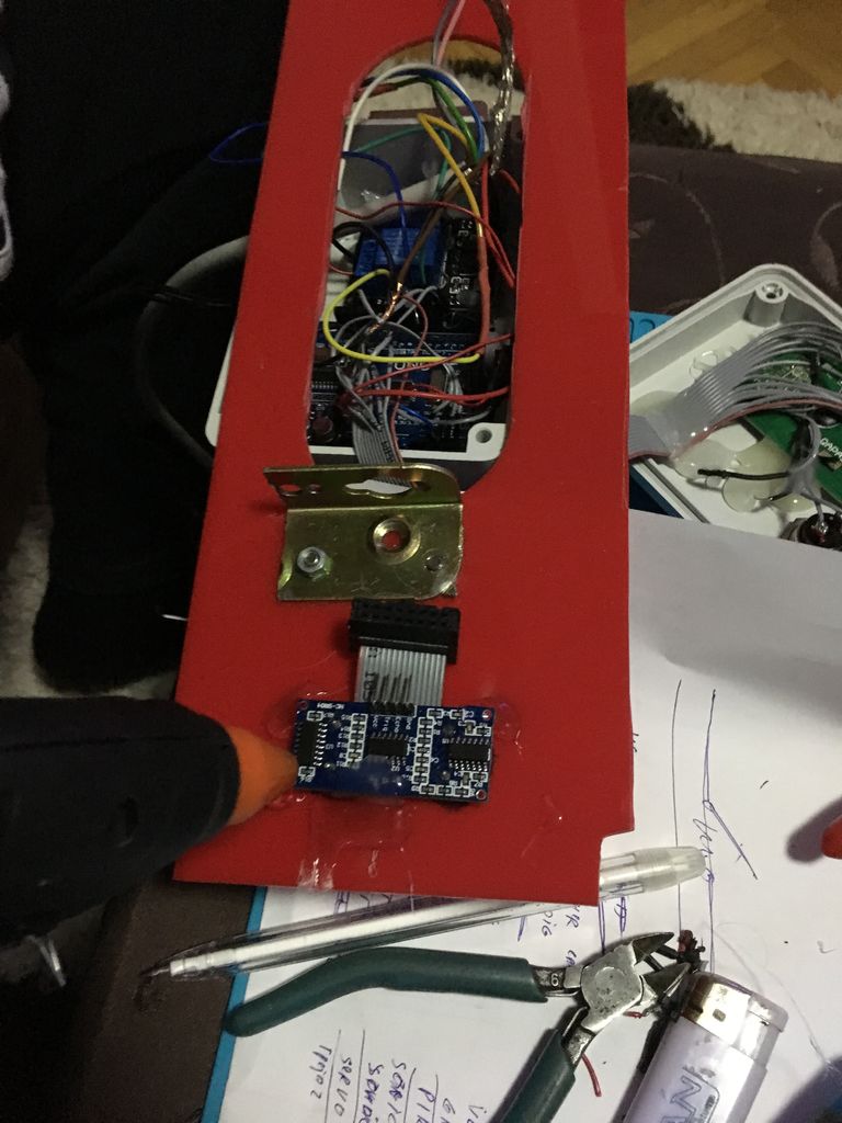
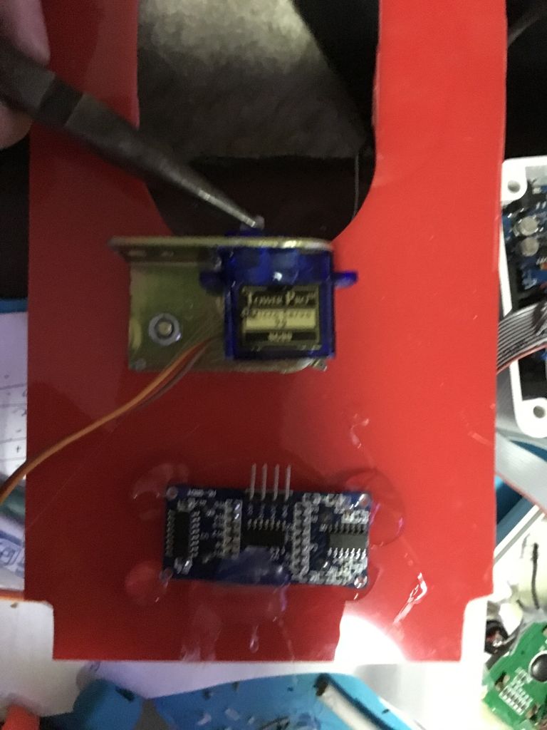
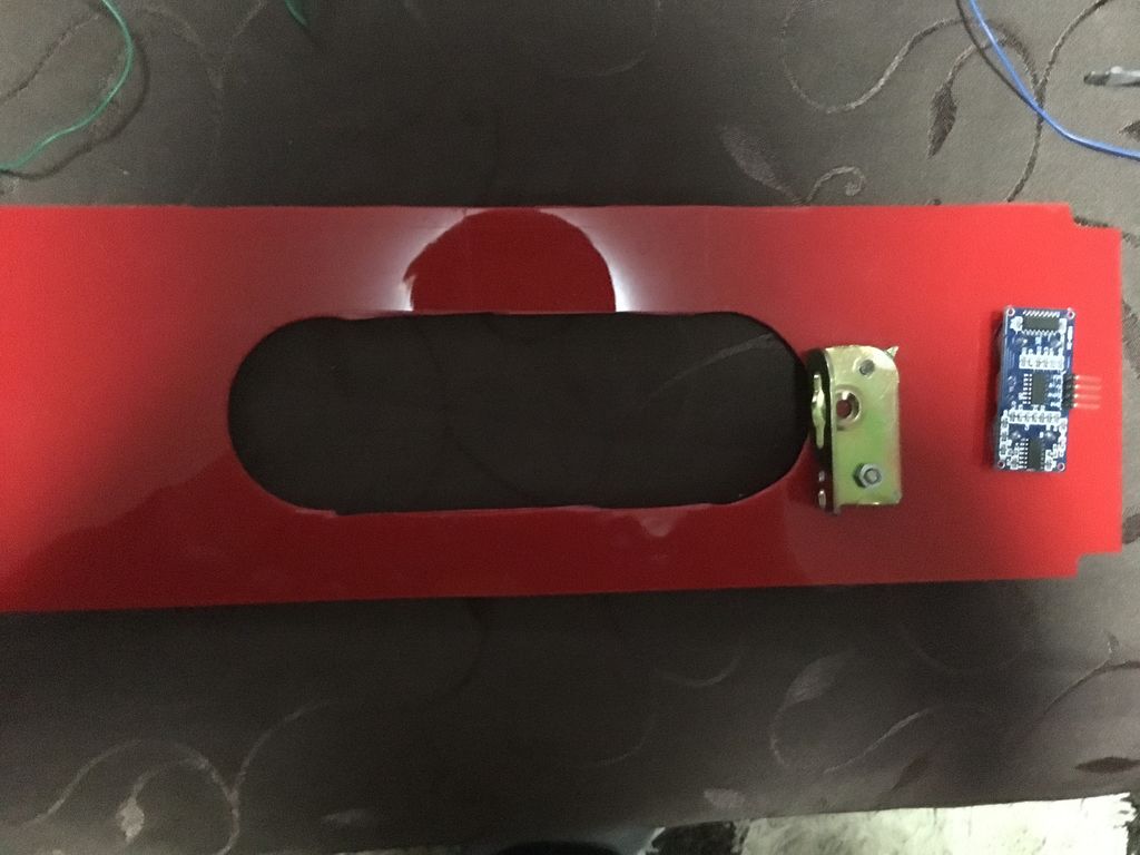
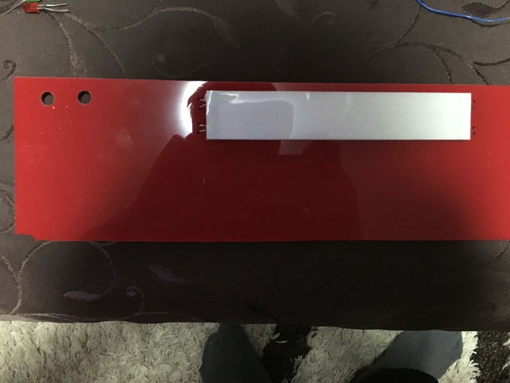
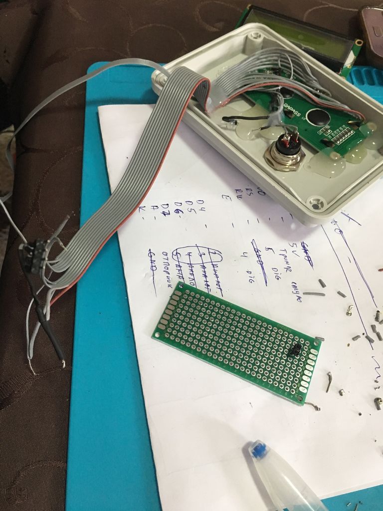
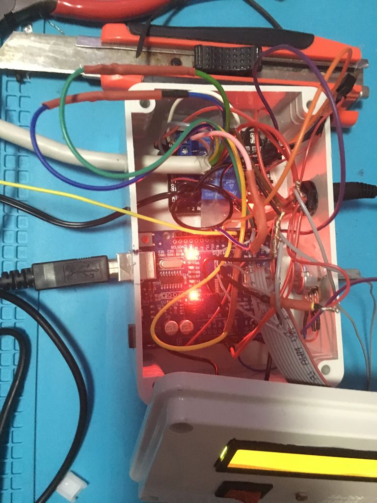
从图片中我们可以看到,我们有一个带孔的红色塑料板,它是金属盒的一部分在水族馆上方。在那个洞里,带有伺服系统的Magnesium Tablet Box会不时地旋转以喂鱼。有机玻璃中的LED二极管粘在电路板上,所以当它变暗时,它会通过光敏电阻激活。电路板上的另一个传感器是超声波传感器,通过电路板的孔,水温传感器将进入水中。
首先,我们将开始将水温传感器与Arduino连接。由于我们在Arduino的盒子上钻了一个洞(查看以前部件的图片),我们不需要额外的电线来连接。来自传感器的GND线连接到Arduino上的GND引脚,来自传感器的VCC线连接到VCC引脚,来自传感器的数据线连接到Arduino上的数字引脚8。然而,数据线也与来自传感器的VCC线连接,与4.7k欧姆电阻焊接在一起。
接下来是超声波传感器。该传感器通过DS电缆的4根线连接(请参阅前一部分)。 VCC线与Arduino的VCC和传感器的VCC引脚相连。 GND线连接Arduino的GND和传感器的GND。其余2根线用于传感器的Echo和Trigger引脚。 Echo引脚连接在Arduino上的数字引脚7上,触发引脚分别通过导线连接到Arduino上的数字引脚6上。但是,我们需要钻两个孔,这样超声波的“眼睛”就会指向水面。
之后是伺服电机。我们将取出伺服的旋转盖,我们将用镁盒盖替换它。伺服的连接很简单。 DS电缆的VCC线与伺服的VCC线连接,电缆的GND线与伺服的GND线连接,伺服的数据线通过Arduino上的数字引脚9连接。电线离开了。
最后它出现了有机玻璃中的LED二极管。从技术上讲,有机玻璃中有4个LED。但在这里我们不需要电阻器。在这里,来自LED的阳极与DS电缆的剩余电线之一焊接在一起,其末端连接到数字引脚12.Kathodes与GND电线焊接在一起,并与GND连接Arduino上的pin。
第5步:结论
代码:
#include
#include
#include
#include
//digital pin 8 for data for DS18B20 water temperature sensor
#define ONE_WIRE_BUS 8
//digital pin 10 for relay1
#define RELAY1 10
//digital pin 2 for relay2
#define RELAY2 2
OneWire oneWire(ONE_WIRE_BUS);
// initialize the library by associating any needed LCD interface pin
// with the arduino pin number it is connected to
const byte rs = 5, en = 4, d4 = 16, d5 = 17, d6 = 18, d7 = 19;
byte trigPin = 6; // Trigger
byte echoPin = 7; // Echo
byte servoPin = 9; // Servo
byte light = 12; // Light
byte photocellPin = 1; //Photoresistor (analog pin 1)
Servo servo;
LiquidCrystal lcd(rs, en, d4, d5, d6, d7);
DallasTemperature sensors(&oneWire);
int i=0;
int val = 0; //analog value from photoresistor
int cm; //water level distance in cm
float Celsius = 0; // Water temperature
int servoAngle = 0; // Servo angle
unsigned long lastOccur = 0; // last time the servo was called (in milliseconds)
unsigned long current; // keep track of current time (in milliseconds)
void setup(){
Serial.begin(9600);
// set up the LCD‘s number of columns and rows:
lcd.begin(16,2);
pinMode(trigPin, OUTPUT);
pinMode(echoPin, INPUT);
servo.attach(servoPin);
pinMode(RELAY1, OUTPUT);
digitalWrite(RELAY1, HIGH);
pinMode(RELAY2, OUTPUT);
digitalWrite(RELAY2, HIGH);
pinMode(light, OUTPUT);
}
void loop(){
//Check time (used as timer for the servo)
current = millis();
//Read the value from the analog pin from the photoresistor
val = analogRead(photocellPin);
//Calculate the temperature in celsius
Celsius = calcTemp();
// Convert the time into a distance
cm = ultrasonic_distance();
// Print the temperature and water level
printLCD(cm,Celsius);
//Activate pump if water level is less than 18 cm
if(cm 》 18){
pump();
}
// Activate heater if temperature is below 22 degrees celsius
if(Celsius 《 22){
heat();
}
// Activate light
if(val 《= 412){
digitalWrite(light, HIGH);
}
else{
digitalWrite(light, LOW);
}
//timer 30s
if(current - lastOccur 》= 30000){
callServo();
lastOccur=millis();
}
}
float calcTemp() {
sensors.requestTemperatures();
// returns the temperature in celsius
return sensors.getTempCByIndex(0);
}
int ultrasonic_distance(){
// Clears the trigPin
digitalWrite(trigPin, LOW);
delay(0.002);
//Sets the trigPin on HIGH state for 10 micro seconds
digitalWrite(trigPin, HIGH);
delay(0.01);
digitalWrite(trigPin,LOW);
return calcDistanceInCm(pulseIn(echoPin, HIGH));
}
int calcDistanceInCm(long dur){
//divide by 29.1 or multiply by 0.0343
return (dur/2)*0.0343;
}
void heat(){
delay(1000); // wait 1 second
digitalWrite(RELAY2, LOW); // turn on relay2
delay(5000); //wait for 5 seconds
digitalWrite(RELAY2, HIGH); // turn off relay2
delay(1000); // wait 1 second
}
void pump(){
delay(1000); //wait 1 second
digitalWrite(RELAY1, LOW); // turn on relay1
delay(20000); // wait 20 seconds
digitalWrite(RELAY1, HIGH); // turn off relay1
delay(1000); // wait 1 second
}
void printLCD(int cm, float temp){
lcd.clear();
// set the cursor to column 0, line 0
// (note: line 0 is the first row, since counting begins with 0):
lcd.setCursor(0, 0);
lcd.print(“Distance: ”);
//print the water level in cm
lcd.print(cm);
lcd.print(“cm”);
lcd.setCursor(0, 1);
lcd.print(“Temperature:”);
//print the temperature in celsius
lcd.print((int)temp);
lcd.print((char)223);
lcd.print(“C”);
delay(1000)
}
void callServo(){
for(i=0;i《2;i++){
for(servoAngle = 0; servoAngle 《 180; servoAngle++){ // move the micro servo from 0 degrees to 180 degrees
servo.write(servoAngle);
delay(7); // servo start speed (faster)
}
delay(2000);
for(servoAngle = 180; servoAngle 》 0; servoAngle--){ // now move back the servo to 0 degrees
servo.write(servoAngle);
delay(10); //servo back speed (slower)
}
}
}
-
[原创]2009年美国芝加哥宠物用品展览会/2009年美国芝加哥宠物水族展览会2009-06-11 0
-
7通道海洋暗礁水族馆LED显示屏2022-08-01 0
-
DIY水族箱控制器2022-08-03 0
-
让水下生物感觉回到大自然的传感器水族馆2018-06-15 1767
-
海多宝水族馆区块链模式平台系统开发2018-08-03 253
-
自制水族灯diy图解2018-09-10 11280
-
自制简易的水族箱温控器2019-02-14 10735
-
带Arduino的水族馆灯PWM的制作2019-10-29 1803
-
艾迈斯欧司朗为水族馆的入口顶篷打造照明方案2022-04-13 4638
-
物联网水族馆喂鱼器开源2022-11-17 340
-
基于Atlas Scientific的水族箱蒸发补水系统2022-12-16 204
-
Arduino UNO水族馆自动化2023-07-06 189
-
水族馆饲养区追踪器开源分享2023-07-13 196
全部0条评论

快来发表一下你的评论吧 !
