

如何制作监控摄像机
电子说
描述
第1步:我们需要什么
物理计算
Arduino Uno(或另一个工作的微控制器)
伺服(我使用parralax标准伺服)
Red led
220k电阻
5x电线
Javascript
P5.js
P5 DOM库
P5串行库
P5串行控制(处理串行通信的小程序)
ML5.js
对象
MDF 4mm
底漆喷涂
白色喷漆
浅灰色喷涂油漆
黑色喷漆
黑色太阳镜镜片(或其他)
第2步:进行姿势估计工作
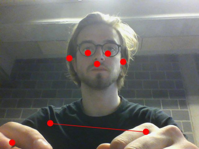
首先我们要编写识别人类的草图并在它的鼻子上放一个点。目标是从这一点获取水平X数据并将其发送到Arduino。
让我们开始吧!
在这个项目中,我们需要一些文件或库来使一切正常工作:
p5.js (您可以下载完整的软件包,因为这包括DOM库)
p5 DOM
p5串口(我使用了包中包含的示例中的p5.serialport.js文件) )
ML5.js(您可以将其作为链接包含在内,或者您可以通过这种方式下载整个本地库,这样您就不需要连接互联网以使一切正常工作)
我们拥有所有这些,我们可以将所有内容链接到一个简单的HTML文件中:
接下来是我们的sketch.js文件,其中所有的魔法都发生了!
var serial;
var portName = ‘COM6’; // fill in your serial port name here, you can check the right port in Arduino or P5 serial control
var options = {
baudrate: 19200 //baudrate has to be the same in arduino
};
// this is the message that will be sent to the Arduino:
var oneMessage;
let video;
let poseNet;
let poses = [];
var noseX = []
var ifPerson = true;
//var flipHorizontal = false;
function setup() {
createCanvas(640, 480);
video = createCapture(VIDEO);
video.size(width, height);
frameRate(10);
//--------------------------------------
serial = new p5.SerialPort();
// Get a list the ports available
// You should have a callback defined to see the results. See gotList, below:
serial.list();
// Assuming our Arduino is connected, open the connection to it
serial.open(portName, options);
// When you get a list of serial ports that are available
serial.on(‘list’, gotList);
// When you some data from the serial port
serial.on(‘data’, gotData);
//-----------------------------------------
// Create a new poseNet method with a single detection
poseNet = ml5.poseNet(video, {
flipHorizontal: true,
detectionType: ‘single’
}, modelReady);
// This sets up an event that fills the global variable “poses”
// with an array every time new poses are detected
poseNet.on(‘pose’, function (results) {
poses = results;
if (results.length == 0) {
ifPerson = false;
}
//console.log(‘results: ’ + results);
});
// Hide the video element, and just show the canvas
video.hide();
}
function modelReady() {
select(‘#status’).html(‘Model Loaded’);
}
function draw() {
image(video, 0, 0, width, height);
// We can call both functions to draw all keypoints
drawKeypoints();
if (ifPerson == false) {
serial.write(‘c’);
console.log(“X”);
ifPerson = true;
} else {
oneMessage = map(oneMessage, 1, 640, 65, 115);
serial.write(oneMessage);
console.log(“browser: ” + oneMessage);
}
}
//---------------------------------
// Got the list of ports
function gotList(thelist) {
console.log(“List of Serial Ports:”);
// theList is an array of their names
for (var i = 0; i 《 thelist.length; i++) {
// Display in the console
console.log(i + “ ” + thelist[i]);
}
}
// Called when there is data available from the serial port
function gotData() {
var currentString = serial.readLine();
console.log(currentString);
}
//-------------------------------------
// A function to draw ellipses over the detected keypoints
function drawKeypoints() {
// Loop through all the poses detected
for (let i = 0; i 《 poses.length; i++) {
// For each pose detected, loop through all the keypoints
for (let j = 0; j 《 poses[i].pose.keypoints.length; j++) {
// A keypoint is an object describing a body part (like rightArm or leftShoulder)
let keypoint = poses[i].pose.keypoints[“0”];
noseX[i] = keypoint.position.x.toFixed(0);
oneMessage = (parseInt(noseX[0],10));
//console.log(typeof(oneMessage));
select(‘#noseX_1’).html(noseX.toString());
//console.log(typeof(oneMessage))
// Only draw an ellipse is the pose probability is bigger than 0.2
if (keypoint.score 》 0.2) {
fill(255, 0, 0);
noStroke();
ellipse(keypoint.position.x, keypoint.position.y, 10, 10);
}
}
}
}
就是这样!如果您打开html文件,您将看到网络摄像头镜头上方有一个红点但镜像(否则您的伺服将远离您)。您还将看到发送到Arduino的X数据
第3步:使用P5.serialcontrol
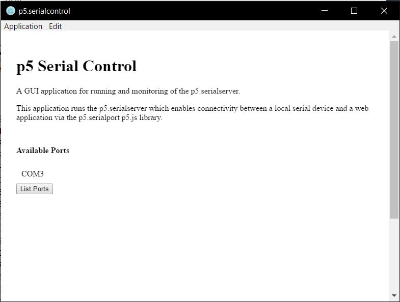
这是一个快速的。为了建立我的草图和Arduino之间的串行通信,我们需要一个处理所有串行数据的中间人将它发送到另一个。以前人们会使用不太友好的Node.js,p5.serialcontrol修复了这个问题。你可以在这里下载p5.serialcontrol。对于Windows用户,请查看Alpha 5版本。
可悲的是,p5.serialcontrol并不完美,有时会崩溃。所以要小心你发送了多少数据。
步骤4:一切Arduino
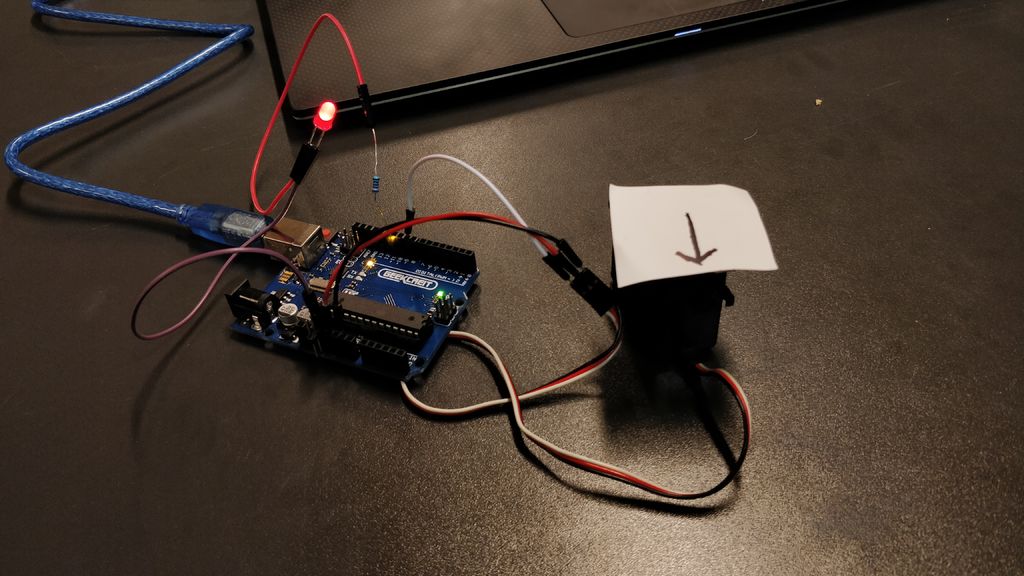
接下来是Arduino代码并连接伺服和LED。
#include
Servo myservo;
const int redPin = 12;
int newval1, oldval1;
int servoValue;
int space = 2;
int ledState = LOW;
int pos = 0;
unsigned long currentMillis = 0; // stores the value of millis() in each iteration of loop()
unsigned long previousServoMillis = 0; // the time when the servo was last moved
unsigned long previousMillis = 0;
const long interval = 500;
int servoPosition = 90;
int servoSlowInterval = 60; // millisecs between servo moves
int servoFastInterval = 10;
int servoInterval = servoSlowInterval; // initial millisecs between servo moves
int servoDegrees = 2; // amount servo moves at each step
int servoMinDegrees = 45; // will be changed to negative value for movement in the other direction
int servoMaxDegrees = 135;
int increment; // increment to move for each interval
int updateInterval; // interval between updates
unsigned long lastUpdate; // last update of position
int counter = 0;
bool executed = false;
void servoSweep() {
if (currentMillis - previousServoMillis 》= servoInterval) {
previousServoMillis += servoInterval;
servoPosition = servoPosition + servoDegrees; // servoDegrees might be negative
if (servoPosition 《= servoMinDegrees) {
// when the servo gets to its minimum position change the interval to change the speed
if (servoInterval == servoSlowInterval) {
servoInterval = servoSlowInterval; //servoFastInterval
}
else {
servoInterval = servoSlowInterval;
}
}
if ((servoPosition 》= servoMaxDegrees) || (servoPosition 《= servoMinDegrees)) {
// if the servo is at either extreme change the sign of the degrees to make it move the other way
servoDegrees = - servoDegrees; // reverse direction
// and update the position to ensure it is within range
servoPosition = servoPosition + servoDegrees;
}
// make the servo move to the next position
myservo.write(servoPosition);
digitalWrite(redPin, LOW);
// and record the time when the move happened
}
void ledBlink () {
if (currentMillis - previousMillis 》= interval) {
previousMillis = currentMillis;
if (ledState == LOW) {
ledState = HIGH;
} else {
ledState = LOW;
}
digitalWrite(redPin, ledState);
}
}
void setup() {
myservo.attach(9); // servo
Serial.begin(19200); // initialize serial communication
//Serial.setTimeout(10);
pinMode(redPin, OUTPUT);
myservo.write(90);
}
void loop() {
currentMillis = millis();
if (executed == false) {
servoSweep();
delay(50);
}
}
void serialEvent () {
while (Serial.available()) {
newval1 = Serial.read(); //read it
//Serial.println(newval1);
if (newval1 》 0 && newval1 != ‘c’) {
executed = true;
ledBlink();
//if (newval1 《 (oldval1 - space) || newval1 》 (oldval1 + space)) { //dead band setup
myservo.write(newval1);
delay(15);
//oldval1 = newval1;
//}
}
if (newval1 == ‘c’) {
executed = false;
}
}
}
正如您所看到的,我使用了不使用delay()的代码,因此可以随时停止扫描功能,即如果某人被识别。
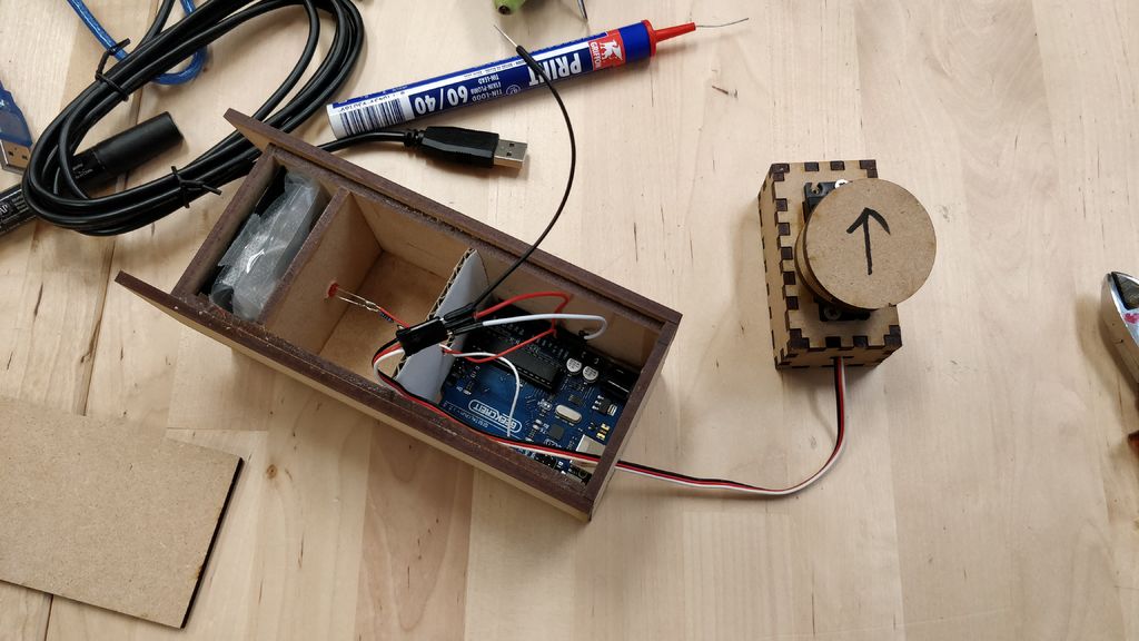
在此之后,您可以测试整个系统。首先插入你的Arduino与led和伺服(我在我的箭头上进行测试),然后启动p5.serialcontrol然后打开html文件。如果一切正常,箭头将始终指向您。如果您走出网络摄像头捕获的图像,伺服将扫描。
第5步:制作安全摄像头
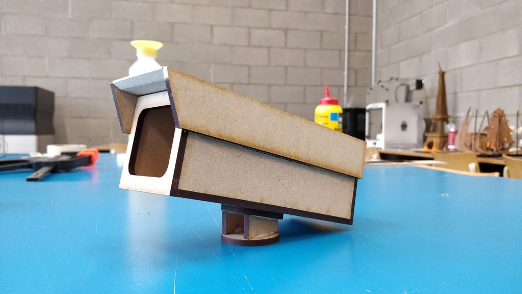
所有这些软件和代码都让我们开始制作东西!
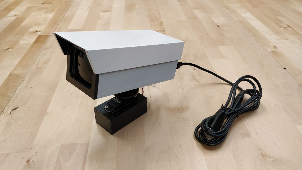
我模仿了安全摄像头的这个原型,并为激光切割机设计了它。我用木胶组装了这些碎片。相机内部有足够的空间容纳Arduino,它需要一些额外的孔才能将所有电线都放入其中。我还将LED放置在正确的位置,并在前面安装了黑色镜头,以提供额外的安全摄像头效果。我用一些塑料薄膜消除了led灯的光线。
接下来,我准备整个事情并用典型的安全摄像头颜色绘制它。
步骤6:安装备注
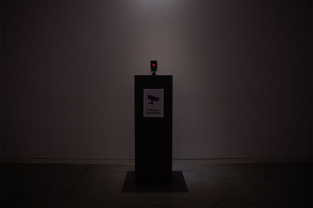
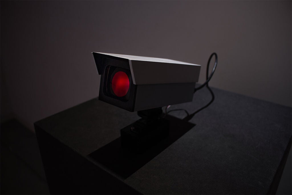
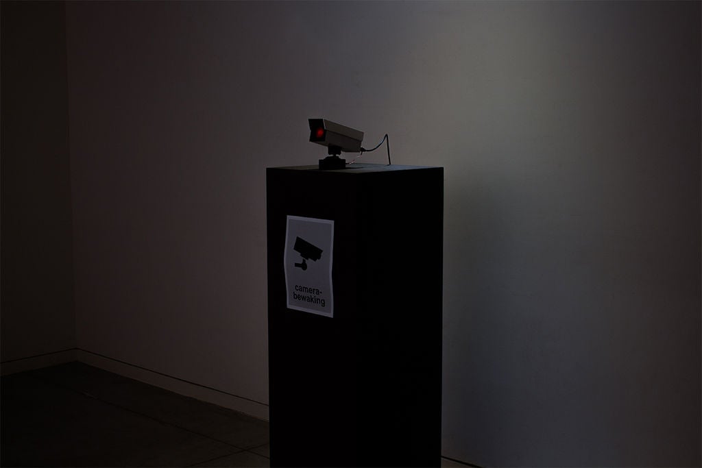
关于在某处设置此安装的最后一些评论。安全摄像头本身没有摄像头摄像头,可以看到前面的人。我所做的是将网络摄像头隐藏在支柱中并在其前面放置一个带孔的海报,以隐藏相机,这对于创造正确的效果至关重要。
您还可以做的就是放置相机处于一个更典型的安全摄像头位置,就像挂在天花板或墙壁上一样。但你可以用它做任何你想做的事!
第7步:结束结果
- 相关推荐
- 监控摄像机
-
监控摄像机的同步方式选择法2008-10-06 0
-
深入了解红外摄像机2009-02-05 0
-
监控摄像机在家庭监控的安装原理2009-03-13 0
-
网络摄像机是什么?2009-05-26 0
-
[原创]浅谈监控摄像机的技术原理与应用2010-06-30 0
-
如何识别监控摄像机品质?2011-02-23 0
-
全景监控摄像机四大特性2012-10-11 0
-
摄像机电源如何配置2012-10-30 0
-
POE网络摄像机功能介绍及监控应用2014-05-13 0
-
MS41918M网络摄像机·监控摄像机用镜头驱动芯片(内置光圈控制)2019-07-29 0
-
MS41909 网络摄像机,监控摄像机用镜头驱动马达芯片2019-09-06 0
-
网络摄像机与模拟摄像机的区别是什么2020-12-11 0
-
MS41908M 网络摄像机·监控摄像机用镜头驱动芯片(内置光圈控制)2021-02-28 0
-
高级互联网协议(IP)摄像机与模拟摄像机的应用有何差异?2021-06-02 0
全部0条评论

快来发表一下你的评论吧 !
