

如何通过ESP8266和各种传感器创建天气和空气质量监视器
电子说
描述
步骤1:所需的组件
以下组件列表用于构建天气和空气质量监视器。您也可以使用功能相同的组件。
ESP8266 D1 Mini
TFT ILI9341 240x320 SPI接口
锂电池
锂电池USB充电模块
3.3V输出DC-to-DC模块
5V输出DC-to-DC模块
小型开关x 2
HDC1080湿度传感器
BMP180温度和气压传感器
CCS811 TVOC传感器
SenseAir S8 CO2传感器
PM2。 5/PM10红外传感器
电路板,自动换线工具和电线
步骤2:构建电源电路
1。将锂电池,电池充电器,3.3V和5V DC-DC转换器连接在一起。您可能想在锂电池与3.3V和5V DC-DC电源转换器之间添加一个ON/OFF开关。
2。测试锂电池是否可以充电。
3。确认可以获得稳定的3.3V和5V电源。
步骤3:为各种用途分配ESP8266 D1迷你引脚
首先,创建您的设计。为各种目的分配ESP8266 D1迷你引脚。 D1 Mini的针脚数量有限,我们需要仔细进行分配。那些可以保存大头针的应该被保存。例如,某些传感器只会通过TTL发送数据,而不会接收数据,因此我们不需要将接收引脚连接到D1 Mini。
以下是我的引脚分配:
/* PIN Assignment
A0 - Not Used
D0 - TFT CS
D1 - I2C CLK
D2 - I2C SDA
D3 - TFT C/D
D4 - PM2.5 CS
D5 - TFT SCK
D6 - S8 SenseAir TX+RX tied
D7 - TFT SDI(MOSI)
D8 - Not Used
TX - Debug Console
RX - PM2.5 Tx
*/
步骤4:通过SPI总线将D1 Mini与240x320 TFT相连
连接D1带有SPI总线的240x320 TFT微型。使用以下引脚:
D0 - TFT CS
D3 - TFT C/D
D5 - TFT SCK
D7 - TFT SDI(MOSI)
请注意,MISO引脚未接线。原因是我们使用的TFT库不会从TFT获取任何数据。因此,我们可以节省1针用于其他用途。 UTFT ESP8266库用于在SPI模式下驱动支持ILI9341的TFT。如果您的TFT使用其他芯片组,则可能需要使用其他TFT库。关键是您需要选择一个支持SPI总线的TFT。否则,D1 Mini将没有足够的引脚与之连接。
要与TFT一起成功运行,关键是要以正确的格式正确声明UTFT对象。这是我们使用的方法:
// TFT Display
#include
#include
// UTFT::UTFT(byte model, int RS=SDI(MOSI), int WR=SCK, int CS=CS, int RST=NOTINUSE, int SER=DC)
UTFT myGLCD ( ILI9341_S5P, D7, D5, D0, NOTINUSE, D3); //ILI9341 in SPI
步骤5:将湿度传感器连接到I2C总线
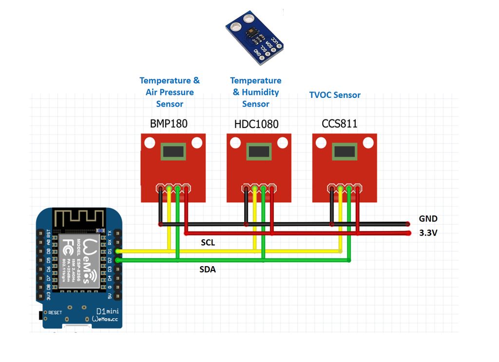
ESP8266 D1 Mini支持IIC总线。引脚D1用于时钟(SCL或CLK),引脚D2用于数据(SDA)。 IIC总线可以同时支持位于不同地址的多个设备。您可以将传感器连接到3.3V电源以及D1 Mini的SCL和SDA酒吧。
HDC1080用于感测湿度。我们使用 ClosedCube库。
temperature[idx] = hdc1080.readTemperature();
if ( temperature[idx] 》 80.0) //Abnormal Reading, reset the chip
hdc1080.reset();
Serial.print(“HDC_Temp = ”); Serial.print(temperature[idx]); Serial.print(“ ”);
//-------------------------------
humidity[idx] = hdc1080.readHumidity();
Serial.print(“HDC_Humidity = ”); Serial.print(humidity[idx]); Serial.print(“ ”);
步骤6:将温度和气压传感器连接至IIC总线
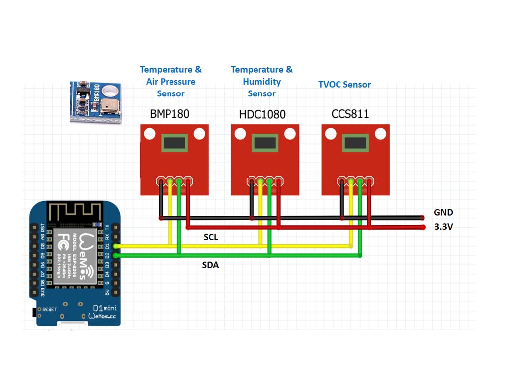
ESP8266 D1 Mini支持IIC总线。引脚D1用于时钟(SCL或SCK),引脚D2用于数据(SDA)。 IIC总线可以同时支持位于不同地址的多个设备。您可以将传感器与3.3V电源以及D1 Mini的SCL和SDA酒吧相连。
BMP180用于感测温度和气压。我们使用 Sparkfun库。
if ((status = bmp180.startTemperature()) != 0) {
delay(status);
if (bmp180.getTemperature(T) != 0) {
temperature[idx] = T; // Over-ride the inaccurate temperature from HDC1080
if ((status = bmp180.startPressure(3)) != 0) {
delay(status);
if (bmp180.getPressure(P, T) != 0)
pressure[idx] = P;
}
}
}
Serial.print(“bmp180Temp = ”); Serial.print(temperature[idx]); Serial.print(“ ”);
Serial.print(“PRS = ”); Serial.print(pressure[idx]); Serial.print(“ ”);
步骤7:将TVOC传感器连接到IIC总线
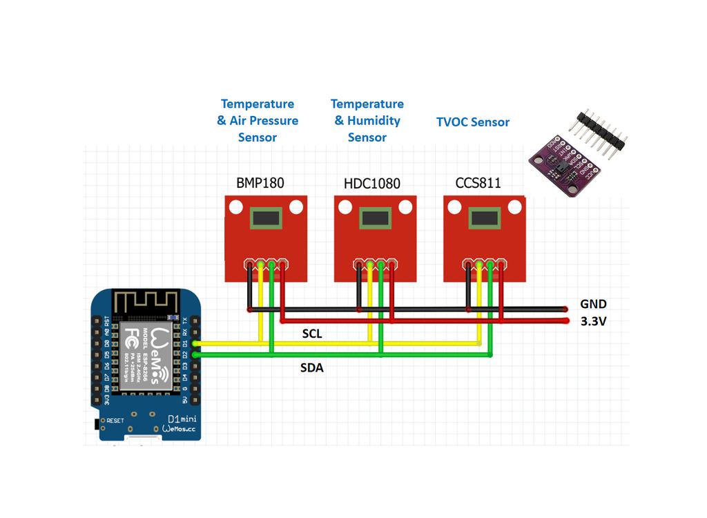
ESP8266 D1 Mini支持IIC总线。引脚D1用于时钟(SCL或SCK),引脚D2用于数据(SDA)。 IIC总线可以同时支持位于不同地址的多个设备。您可以将传感器与3.3V电源以及D1 Mini的SCL和SDA酒吧相连。
我们使用的TVOC传感器是CCS811, Adafruit库可以读取数据。
但是,我们需要注意CCS811的自校准过程,以便快速获取数据。添加了一个额外的例程以将BASELINE数据记录在ESP8266的EEPROM中。 CCS811会自动连续调整BASELINE。我们定期将BASELINE记录到EEPROM。在下一次系统启动时,我们在CCS811预热后读入最后记录的BASELINE。详细逻辑可从CCS811数据表中获得。
示例代码如下:
setup(){
// Sensor Initilization
hdc1080.begin(0x40);
hdc1080.reset();
bmp180.begin();
ccs811.begin();
S8Serial.begin(9600);
S8_begin(&S8Serial);
//==== CCS811 BASELINE MANAGEMENT ====
EEPROM.begin(512);
copyCurrentTime(&curr_epoch, &curr_remain_millis); // Get the current time in Epoch
if (startup_epoch == 0) // initialize startup_epoch = curr_epoch;
if (last_eeprom_write_epoch == 0) // initialize
last_eeprom_write_epoch = curr_epoch;
// Read all the BASELINE records and pick the best one to use
score = 0; best_score = 0; lowest_score = 4294967295; //2^32-1
for (int j = 0; j 《 BASELINEREC_MAX; j++) { // Check all records in the EEPROM
// Read the BASELINE record
int baselinerec_addr_read = sizeof(uint16_t) + sizeof(struct baselinerec) * j;
for (int i = 0; i 《 sizeof(struct baselinerec); i++)
* ((uint8_t*)&_baselinerec_read + i) = (uint8_t)EEPROM.read(baselinerec_addr_read + i);
// Calculate the score of each record
if (_baselinerec_read.signature != 0xABAB) // record not initialized
score = 0;
else if ( (curr_epoch - _baselinerec_read.epoch) 》 28 * 24 * 3600) // record too old
score = 0;
else if ( _baselinerec_read.uptime 《 4 * 3600) // record was obtained over a too short period
score = 0;
else // score formula can be customized
score = _baselinerec_read.uptime + ((28 * 24 * 3600 - (curr_epoch - _baselinerec_read.epoch)) / 2);
Serial.print(“j=”); Serial.print(j);
Serial.print(“ signature=”); Serial.print(_baselinerec_read.signature);
Serial.print(“ epoch=”); Serial.print(_baselinerec_read.epoch);
Serial.print(“ uptime=”); Serial.print(_baselinerec_read.uptime);
Serial.print(“ avg_tvoc=”); Serial.print(_baselinerec_read.avg_tvoc);
Serial.print(“ score=”); Serial.println(score);
delay(100); // prevent D1 Mini software reset due to too much I/O
// Select the one with the highest score for read
if (score 》 best_score) {
best_score = score;
baseline_idx_read = j;
}
// Select the one with the highest score for write
if (score 《 lowest_score) {
lowest_score = score;
baseline_idx_write = j;
}
}
Serial.print(“baseline_idx_read=”); Serial.print(baseline_idx_read);
show_text(“baseline_idx_read=%.0f”, (float)baseline_idx_read, GEN_COLOR, CHART_LEFT, CHART_TOP + 96, 0);
Serial.print(“ baseline_idx_write=”); Serial.println(baseline_idx_write);
show_text(“baseline_idx_write=%.0f”, (float)baseline_idx_write, GEN_COLOR, CHART_LEFT, CHART_TOP + 112, 0);
// Read in the best record
if (best_score != 0) {
int baselinerec_addr_read = sizeof(uint16_t) + sizeof(struct baselinerec) * baseline_idx_read;
for (int i = 0; i 《 sizeof(struct baselinerec); i++)
* ((uint8_t*)&_baselinerec_read + i) = (uint8_t)EEPROM.read(baselinerec_addr_read + i);
}
// update the eeprom baseline index to record where is the current record
if (eeprom_baseline_idx_updated == false) {
EEPROM.write(0, baseline_idx_write 》》 8);
EEPROM.write(1, (baseline_idx_write 《《 8) 》》 8);
eeprom_baseline_idx_updated = true;
}
EEPROM.commit();
}
//The code below should be put in the loop() part of the sketch to write the lastly recorded BASELINE to CCS811
//and record the tunned BASELINE periodically.
//==== CCS811 BASELINE MANAGEMENT ====
// Get curr_epoch & uptiime for the operation below
copyCurrentTime(&curr_epoch, &curr_remain_millis);
uptime = curr_epoch - startup_epoch;
// write the best BASELINE to CCS811 after uptime 》 X minutes
if (ccs811_baseline_updated == false && best_score != 0 && uptime 》= 600) {
ccs811.writeBaseline(_baselinerec_read.baseline);
ccs811_baseline_updated = true;
}
// write to EEPROM periodically - Y minutes
uint8_t baseline[2];
ccs811.readBaseline(baseline);
if ( curr_epoch - last_eeprom_write_epoch 》= 900) {
_baselinerec_write.epoch = curr_epoch;
_baselinerec_write.baseline[0] = baseline[0];
_baselinerec_write.baseline[1] = baseline[1];
_baselinerec_write.uptime = uptime;
int baselinerec_addr_write = sizeof(uint16_t) + sizeof(struct baselinerec) * baseline_idx_write;
for (int i = 0; i 《 sizeof(struct baselinerec); i++)
EEPROM.write(baselinerec_addr_write + i, *((uint8_t*)&_baselinerec_write + i));
EEPROM.commit();
last_eeprom_write_epoch = curr_epoch;
}
步骤8:连接PM2.5/PM 10 TTL RX接口的传感器
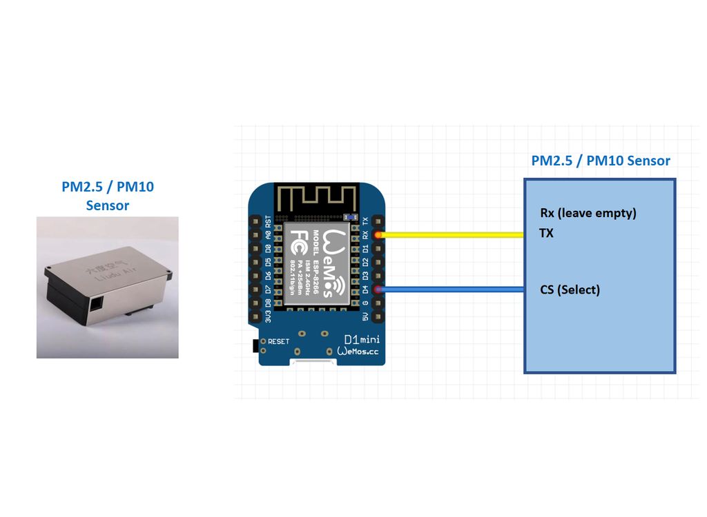
我们使用的传感器来自中国制造商(六度空气)。它通过TTL接口提供数据。每秒生成PM2.5和PM10读数。无需将命令发送到传感器即可触发输出。因此,只需将传感器上的TX引脚和D1 Mini上的RX引脚连接在一起。
请注意,D1 Mini依靠其TX和RX引脚来更新草图。将RX引脚与传感器连接会影响草图下载。因此,在草图下载过程中实现了一个断开RX连接的开关。不使用传感器时,小风扇会消耗功率。传感器处有一个启用(CS)引脚,用于打开/关闭风扇和数据输出。使能(CS)引脚连接到D1 Mini的D4。
以下是从传感器获取数据的代码:
//--------------------------
// PM2.5
//Serial.println(“PM Begin ”);
digitalWrite(PM25_CS, HIGH);
delay(9000); //64 byte buffer only; 7 byte per sample; 64/7=9 max if 1 sec per sample.
while (Serial.available() 》 0) {
do {
incomingByte = Serial.read();
//Serial.print(incomingByte, HEX);
} while (incomingByte != 0xAA);
if (incomingByte == 0xAA) {
Serial.readBytes(buf, 6);
if (buf[5] == 0xFF && (buf[0] + buf[1] + buf[2] + buf[3]) == buf[4]) { //0xFF = term char; checksum
PM2_5Value = ((buf[0] 《《 8) + buf[1]) / 10.0;
PM10Value = ((buf[2] 《《 8) + buf[3]) / 10.0;
}
}
}
//Serial.println(“PM End”);
digitalWrite(PM25_CS, LOW);
pm25[idx] = (float)PM2_5Value;
pm10[idx] = (float)PM10Value;
Serial.print(“PM2.5 = ”); Serial.print(pm25[idx]); Serial.print(“ ”);
Serial.print(“PM10 = ”); Serial.println(pm10[idx]);
步骤9:将CO2传感器连接到软件序列
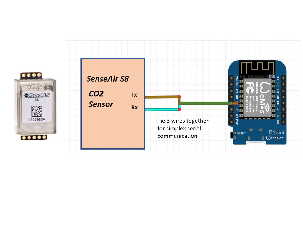
SensorAir S8通过TTL接口输出CO2浓度。由于D1 Mini的RX引脚用于PM2.5/PM 10传感器,因此我们需要使用CO2传感器的软件串行。
D1 Mini没有太多的引脚。我们几乎用完了别针。幸运的是,我们可以将CO2传感器的TX和RX引脚连接在一起,并通过单工模式与之通信。 AirSense S8的数据表中没有对此进行记录,但是可以使用!因此,与CO2传感器通信仅在D1 Mini上消耗了一个引脚。
到目前为止,我们还没有看到来自Internet的用于SensorAir S8的Arduino库。因此,为此目的创建了软件串行功能。首先,我们需要为ABC周期初始化SensorAir S8。然后,我们可以自动从传感器读取CO2值。
初始化代码:
void S8_begin(SoftwareSerialx *ss) {
//byte ch, cmd[] = {0xFE, 0x6, 0x0, 0x1F, 0x0, 0xB4, 0xAC, 0x74}; // Set ABC Period to be 180 hours
//byte ch, cmd[] = {0xFE, 0x6, 0x0, 0x1F, 0x0, 0x30, 0xAC, 0x17}; // Set ABC Period to be 48 hours
byte ch, cmd[] = {0xFE, 0x6, 0x0, 0x1F, 0x0, 0x18, 0xAC, 0x09}; // Set ABC Period to be 24 hours
ss-》enableTx(true);
for (int i = 0; i 《 8; i++)
ss-》write(cmd[i]);
ss-》enableTx(false);
delay(250);
if (ss-》available()) {
Serial.print(“SenseAir Response:”);
while (ss-》available()) {
ch = (byte) ss-》read();
Serial.print(ch 《 0x01 ? “ 0” : “ ”);
Serial.print(ch, HEX);
}
Serial.println();
}
}
读取代码:
int S8_getCO2(SoftwareSerialx *ss, uint16_t*S8_CO2, uint16_t*S8_meterstatus) {
int i;
//byte ch, cmd[] = {0xFE, 0x4, 0x0, 0x03, 0x0, 0x1, 0xD5, 0xC5}; //Get CO2 Only
byte ch, cmd[] = {0xFE, 0x4, 0x0, 0x0, 0x0, 0x4, 0xE5, 0xC6}; //Get MeterStatus and CO2
byte result[20];
ss-》enableTx(true);
for (int i = 0; i 《 8; i++)
ss-》write(cmd[i]);
ss-》enableTx(false);
delay(250);
while (!ss-》available()) // wait until data is available
delay(100);
while ( ss-》available()) {
if ( (ch = ss-》read()) == 0xFE) // wait until the header is available
i = 0;
result[i] = ch;
i++;
}
*S8_CO2 = result[9] * 256 + result[10];
*S8_meterstatus = result[3] * 256 + result[4];
return *S8_meterstatus;
}
步骤10:将草图下载到D1 Mini
将草图下载到D1 Mini并完成。下载草图时,请记住要断开PM2.5/PM10传感器的连接。
步骤11:给电池充电并打开
它将首先连接到WiFi,然后发送NTP数据包并获得Internet时间。然后,扫描其EEPROM以获取CCS811的最佳BASELINE设置。
步骤12:让它自己运行。..
让它自己运行一段时间。您将看到测量的图表和实时指标!!!
责任编辑:wv
-
汽车空气质量检测与改善方案简介2013-07-19 0
-
空气质量传感器MQ135的浓度设定。。。。2014-04-16 0
-
【Tisan物联网申请】室内空气质量监测系统2015-10-15 0
-
STM32空气质量检测应用教程2016-12-29 0
-
空气质量测试仪的原理2018-03-07 0
-
空气质量传感器详解2018-11-08 0
-
空气质量传感器在室内空气清新机中的应用是什么?2021-06-16 0
-
怎样去设计基于STM32的空气质量监测系统2021-08-11 0
-
如何用BME680和ESP866模块制作空气质量传感器?2023-05-19 0
-
无法从串行监视器控制ESP8266怎么解决?2023-05-31 0
-
什么是空气质量传感器_小米空气净化器2空气质量传感器2018-02-27 3442
-
如何利用ESP8266实现便携式空气质量监测站的设计2022-05-14 2710
-
使用ESP8266构建的开源空气质量传感器2022-12-29 324
-
ESP8266空气质量指数显示2023-01-04 250
-
多功能空气质量传感器,我们身边的“空气质量管家”2023-06-01 884
全部0条评论

快来发表一下你的评论吧 !
