

如何使用继电器实现ESP8266的自动化
电子说
描述
步骤1:组装
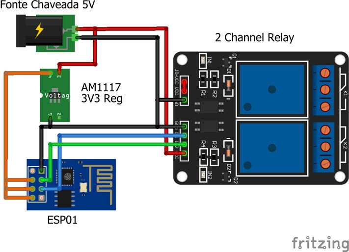
我们组装的电路非常简单,并且组装非常紧凑。我们在后面的区域中使用聚苯乙烯板将所有东西固定在原位。该板还用于辅助电源箱内部的装配,并避免暴露于组件中,因为它可用于控制住宅中的各种设备,例如空调,灯具等。
然后,我们使用开关电源,我将其从110或220伏转换为5伏。我们还有一个3v3稳压器AM1117。我们使用了两个GPIO,并插入了中继板输入。重要的是要记住,使用ESP8266,我们必须采取一些预防措施,例如将引脚接地。
步骤2:Arduino IDE中的ESP8266

重要的是要记住,在编写ESP8266时,需要将此设备的库加载到Arduino中。为此,您应该使用1.6.4版的IDE。现在转到首选项和“其他Board Manager URL”并添加URL:http://arduino.esp8266.com/stable/package_esp8266com_index.json
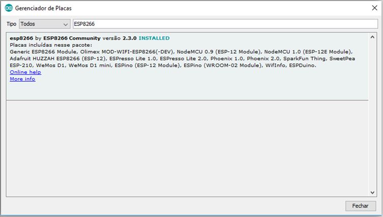
然后,转到Tools》 Boards》 Boards Manager。 。.
在搜索中,输入esp8266并安装“ esp8266 by ESP8266 Community”软件包。
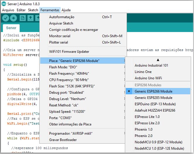
现在,您可以从卡列表中选择ESP8266
***在今天的安装中,ESP866将是一台服务器。因此,您将拿起智能手机,它将连接到设备的IP中,这意味着您可以访问它,并且它将为您提供一个页面。
在视频中,您可以看到有关以下内容的演示:
步骤3:源代码
第一步是包含一个供我们控制ESP8266 WiFi的lib。之后,我们将创建一个变量,该变量将保存对将在端口80上运行的服务器的引用。我们选择端口80的原因是,这是http协议的默认端口,并且我们将使用浏览器连接到
//Includes the lib for Wifi
#include
//Creates a server on port 80 (this is the default port for http requests)
WiFiServer server(80);
步骤4:设置
在设置中,我们将仅初始化Serial,以便使用
我们将使用GPIO0和GPIO2作为输出,并使用LOW初始化初始状态。
void setup()
{
//Initializes the Serial just for logging
Serial.begin(115200);
//Sets GPIO0 and GPIO2 as output, so we can change their value
pinMode(0, OUTPUT);
pinMode(2, OUTPUT);
//Puts the GPIO0 and GPIO2 in LOW output
digitalWrite(0, LOW);
digitalWrite(2, LOW);
我们现在将其称为WiFi.begin(“ ssid”, “ password”)将ESP8266连接到路由器。在该示例中,我们具有ssid“ TestESP”和密码“ 87654321”,但是必须将其替换为将要使用的网络。
Serial.print(“Connecting”);
//Connects to your WiFi network. In this example the SSID is TestESP and the password is 87654321
WiFi.begin(“TestESP”, “87654321”);
我们将每100毫秒检查一次查看ESP8266是否已连接到网络(连接后返回WL_CONNECTED状态)。
When you leave the “while”, it means
that you have connected.
//While our ESP is trying to connect
while (WiFi.status() != WL_CONNECTED)
{
//Waits for 100 milliseconds
delay(100);
Serial.print(“。”);
}
//Here it‘s already connected, so we’ll just show a feedback on Serial Monitor
Serial.println(“”);
Serial.println(“Connected”);
这是我们放置网络设置的位置。 IP,网关和掩码设置必须根据您的网络进行更改。
//Settings for static ip
IPAddress ip(192, 168, 2, 8);
IPAddress gateway(192, 168, 2, 1);
IPAddress subnet(255, 255, 255, 0);
Serial.print(“Static IP is: ”);
Serial.println(ip);
//Sends the settings to the WiFi router
WiFi.config(ip, gateway, subnet);
现在,我们可以初始化服务器并在串行监视器上查看是否链接到ESP8266的IP与我们配置的相同。这是设置的结束。
//Starts the server we created on port 80
server.begin();
//Shows the IP for the server
Serial.print(“Server is on: ”);
Serial.println(WiFi.localIP());
}
步骤5:循环
在程序主循环中,我们会检查是否有任何客户端正在尝试连接,如果连接成功,我们会等到他们返回他们的请求。
void loop()
{
//Checks if there is any client trying to connect
WiFiClient client = server.available();
if (!client)
{
//If there isn‘t, we just return
return;
}
Serial.println(“New Client Connected!”);
我们将请求存储在变量“ req”中,以便以后知道该怎么做
//Reads the request
String req = client.readStringUntil(’ ‘);
Serial.print(“Request: ”);
Serial.println(req);
最后,我们关闭与客户端的连接。这样便完成了循环和代码。
//Closes the connection
client.stop();
Serial.println(“Client disconnected!”);
}
测试
要进行测试,只需打开浏览器并输入将出现在串行监视器上的ip。单击操作,然后查看相应的GPIO是否正在更改。
-
esp8266继电器模块如何使用2021-07-21 0
-
基于ESP8266的继电器2022-08-24 0
-
怎么通过esp8266控制继电器?2023-11-01 0
-
如何使用ESP8266和Android控制继电器2019-07-30 26362
-
调用Lua新建的WEB服务器 操作Nodemcu esp8266 控制继电器实现物联网2021-12-08 567
-
W391180AS1D24_Gerber_PCB_ESP8266带继电器2022-07-11 239
-
ESP8266 4通道继电器2022-07-26 544
-
基于ESP8266的继电器WiFi relay模块2022-08-02 630
-
esp8266三路继电器2023-04-21 209
-
ESP8266 WIFI继电器初识2023-04-21 292
-
51单片机通过WIFI模块ESP8266控制四路继电器2023-04-26 425
-
ESP8266 01S继电器控制智能灯实现2023-04-27 836
-
基于arduino用esp8266和继电器实现小爱同学开关灯2023-05-04 272
-
带有Blynk和IR的Arduino ESP8266控制继电器2023-06-30 510
-
NodeMCU家庭自动化(ESP8266)2023-07-10 248
全部0条评论

快来发表一下你的评论吧 !
