

TI IWR6843单片60- 64-GHzmmWave传感器解决方案
应用案例
描述
TI公司的IWR6843是集成的单片60- 64-GHz mmWave传感器,基于FMCW雷达技术,工作在60-GHz 到 64-GHz波段,采用TI公司的低功耗45nm CMOS工艺制造,非常适合于工业领域的低功耗自监测超精确雷达系统.器件中的FMCW收发器集成了PLL,发送器,接收器,基带和A2D,具有4GHz连续带宽,有四个接收通路,三个发送通路,支持用于TX波束成形的6位相移器,基于分数N PLL的超精确啁啾引擎,发送功率10dBm,接收噪音图14dB,1MHz的相位噪音为–92 dBc/Hz.内置的校准和自测系统采用基于ARM® Cortex®-R4F的无线控制系统,内置的固件(ROM),对频率和温度的自校准系统,用于先进信号处理的C674x DSP,ARM-R4F微控制器用于物体检测和接口控制,支持自主模式,内部存储器具有ECC,主要用在测量范围,速度和角度的工业传感器,建筑物自动化,位移检测,手势,机器人,交通监视,接近和位置检测,安全监控,工厂自动化安全,运动检测,人流统计和占用率检测.本文介绍了IWR6843主要特性,功能框图和时钟子系统,处理器子系统框图以及评估板IWR6843AOPEVM主要特性,框图和天线图,电路图,材料清单和PCB装配图.
The IWR6843 is an integrated single chip mmWave sensor based on FMCW radar technology capable ofoperation in the 60-GHz to 64-GHz band. It is built with TI’s low power 45-nm RFCMOS process andenables unprecedented levels of integration in an extremely small form factor. The IWR6843 is an idealsolution for low power, self-monitored, ultra-accurate radar systems in the industrial space.
IWR6843主要特性:
• FMCW transceiver
– Integrated PLL, transmitter, receiver, Baseband,and A2D
– 60- to 64-GHz coverage with 4-GHz continuousbandwidth
– Four receive channels
– Three transmit channels
– Supports 6-bit phase shifter for TX Beamforming
– Ultra-accurate chirp engine based on fractional-N PLL
– TX power: 10 dBm
– RX noise figure:
– 14 dB
– Phase noise at 1 MHz:
– –92 dBc/Hz
• Built-in calibration and self-test
– ARM® Cortex®-R4F-based radio control system
– Built-in firmware (ROM)
– Self-calibrating system across frequency andtemperature
• C674x DSP for advanced signal processing
• Hardware accelerator for FFT, filtering, and CFARprocessing
• Memory compression
• ARM-R4F microcontroller for object detection, andinterface control
– Supports autonomous mode (loading userapplication from QSPI flash memory)
• Internal memory with ECC
– 1.75 MB, divided into MSS program RAM (512KB), MSS data RAM (192 KB), DSP L1 RAM(64KB) and L2 RAM (256 KB), and L3 radardata cube RAM (768 KB)
– Technical reference manual includes allowedsize modifications
• Other interfaces available to user application
– Up to 6 ADC channels (low sample ratemonitoring)
– Up to 2 SPI ports
– Up to 2 UARTs
– 1 CAN-FD interface
– I2C
– GPIOs
– 2 lane LVDS interface for raw ADC data anddebug instrumentation
• SIL-2 targeted
• Power management
– Built-in LDO network for enhanced PSRR
– I/Os support dual voltage 3.3 V/1.8 V
• Clock source
– 40.0 MHz crystal with internal oscillator
– Supports external oscillator at 40 MHz
– Supports externally driven clock (square/sine) at40 MHz
• Easy hardware design
– 0.65-mm pitch, 161-pin 10.4 mm × 10.4 mm flipchip BGA package for easy assembly and lowcostPCB design
– Small solution size
• Operating conditions:
– Junction temperature range of –40℃ to 105℃
IWR6843应用:
• Industrial sensor for measuring range, velocity,and angle
• Building automation
• Displacement sensing
• Gesture
• Robotics
• Traffic monitoring
• Proximity and position sensing
• Security and surveillance
• Factory automation safety guards
• People counting
• Motion detection
• Occupancy detection
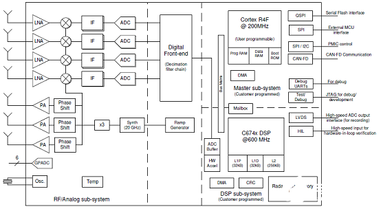
图1.IWR6843功能框图
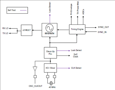
图2.IWR6843时钟子系统
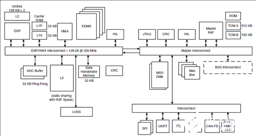
图2.IWR6843处理器子系统框图
评估板MMWAVEICBOOST
The MMWAVEICBOOST Board is combined with the compatible antenna module boards from the starter kit for Industrial Radar Devices of the IWR68xx family.
IWR6843ISK/IWR6843ISK-ODS and MMWAVEICBOOST are part of mmWave EVMs hardware. TheIWR6843 industrial starter kit from Texas Instruments is an easy-to-use evaluation module for theIWR6843 mmwave sensing device. This board contains 60 GHz mmwave Radar transceiver in whichantennas are etched and act as the Radar front-end board. The MMWAVEICBOOST is an add-on boardused with TIs mmWave sensor used in all starter kits to provide more interfaces and PC connectivity tothe mmWave sensors.
The MMWAVEICBOOST board provides an interface for the mmWave Studio toolto configure the Radar device and capture the raw analog-to-digital converter (ADC) data using a captureboard such as DCA1000 evaluation module (EVM). IWR6843ISK and MMWAVEICBOOST containseverything required to start developing software for on-chip C67x DSP core and low-power ARM R4Fcontrollers. It provides interface to the MSP43xx boards through 40-pin LaunchPad™/BoosterPack™connectors.
评估板MMWAVEICBOOST主要特性:
IWR6843ISK
• 60-pin, high-density (HD) connector for raw analog-to-digital converter (ADC) data over LVDS andtrace data capability
Long range on-board antenna
• Current sensors for all rails
• On-board PMIC
IWR6843ISK-ODS (overhead detection sensing)
• 60-pin, high-density (HD) connector for raw analog-to-digital converter (ADC) data over LVDS andtrace data capability
Short range on-board antenna
• Current sensors for all rails
• On-board PMIC
IWR6843AOP
• 60-pin, high-density (HD) connector for raw analog-to-digital converter (ADC) data over LVDS andtrace data capability
Short range on-package antenna
• On-board PMIC
MMWAVEICBOOST
• Hosts starter kit using two 60-pin high-density (HD) connector for the high-speed ADC data over CSI orLVDS and emulator signals
• FTDI-based JTAG emulation with serial port for programming flash on the starter kit
• XDS110-UART based QSPI flash programming
• 60-pin HD connector to interface with the DCA1000 EVM
• Two 20-pin LaunchPad connectors that leverage the ecosystem of the TI standard Launchpad andhave all of the digital controls from the Radar chip
• Two onboard controller area network (CAN) transceivers
• On-board PMIC
• 60-pin MIPI HD connector for JTAG trace
• On-board FTDI chip to provide PC interface for serial peripheral interface (SPI), general-purposeinput/output (GPIO) controls and universal asynchronous receiver/transmitter (UART) loggers
• On-board current sensors and temperature sensors
评估板MMWAVEICBOOS包括:
The following items are included with the EVM kit.
IWR6843ISK
• IWR6843ISK evaluation board
• Warranty card (disclaimer sheet)
• Quick Start Guide
IWR6843ISK-ODS
• IWR6843ISK-ODS evaluation board
• Warranty card (disclaimer sheet)
• Quick Start Guide
IWR6843AOPEVM
• IWR6843AOPEVM evaluation board
• Warranty card (disclaimer sheet)
• Quick Start Guide
MMWAVEICBOOST
• MMWAVEICBOOST evaluation board
• One Micro USB cable for connecting to PC
• Standoffs, screws and nuts for the standalone printed circuit board testing or for mating purpose
• Jumpers
图3.评估板MMWAVEICBOOST外形图
左:正面右:背面
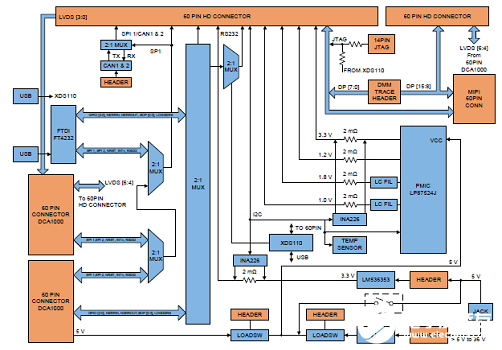
图4.评估板MMWAVEICBOOST框图
硬件特性:
• 1 Micro USB connector for XDS110 Emulator/UART interface
• 1 Micro USB connector for FTDI interface
• One 12-pin dip switch for mux controls
• One push button and two LEDs for basic user interface
• Current sensors for all rails
• 5-V power jack to power the board
• Header for external JTAG connection
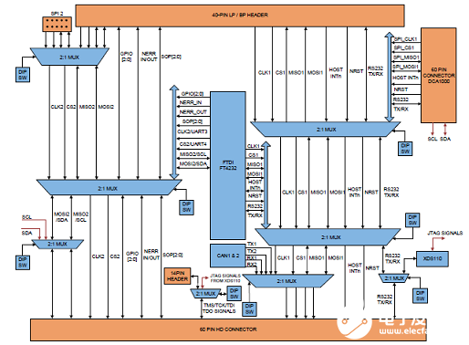
图4.评估板MMWAVEICBOOST框图
图5.PCB天线-正面
图6.PCB天线-背面
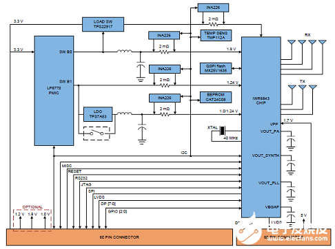
图7.评估板IWR6843ISK/IWR6843ISK-ODS框图
图8.IWR6843ISK-ODS PCB天线图
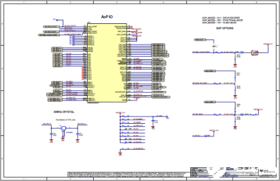
图9.IWR6843AOPEVM正面图
图10.IWR6843AOPEVM背面图
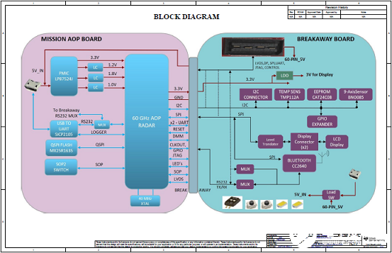
图11.IWR6843AOPEVM框图
图12.IWR6843AOPEVM电路图(1)
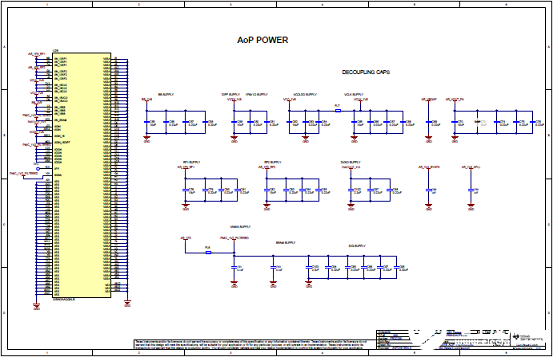
图13.IWR6843AOPEVM电路图(2)
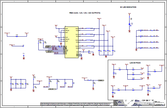
图14.IWR6843AOPEVM电路图(3)
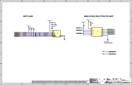
图15.IWR6843AOPEVM电路图(4)

图16.IWR6843AOPEVM电路图(5)
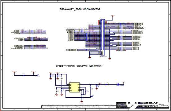
图17.IWR6843AOPEVM电路图(6)
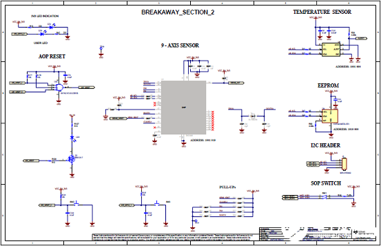
图18.IWR6843AOPEVM电路图(7)
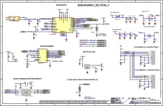
图19.IWR6843AOPEVM电路图(8)
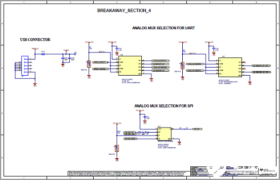
图20.IWR6843AOPEVM电路图(9)
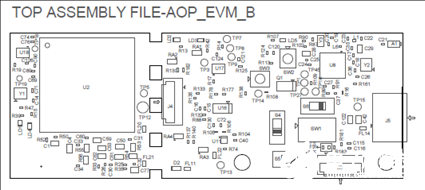
图21.IWR6843AOPEVM PCB设计图(1):顶层装配图
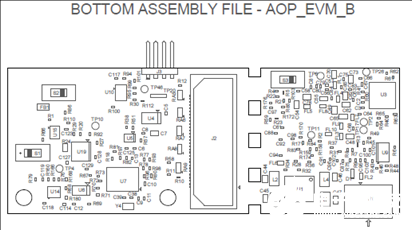
图22.IWR6843AOPEVM PCB设计图(2):底层装配图
-
IWR6843 集成有处理功能的 60GHz 至 64GHz 单芯片智能毫米波传感器2019-01-08 3123
-
【Ti SimpleLink SensorTag申请】TI传感器试用体验2016-03-29 0
-
使用毫米波雷达传感器框图的TIDEP-01000人员计数和跟踪参考设计2018-05-29 0
-
使用TI mmWave叠装天线传感器将传感器尺寸减小多达75% 额外资源2020-11-06 0
-
毫米波传感器的优势是什么2022-11-03 0
-
毫米波雷达传感的成本解决方案2022-11-03 0
-
如何使用60GHz雷达传感器设计汽车车内手势检测系统2022-11-03 0
-
如何使用毫米波传感器进行非接触式私人姿态检测2022-11-08 0
-
演示IWR mmWave传感器在交通中的监控应用2019-03-29 2793
-
控制门或电梯系统的毫米波雷达应用解决方案2020-12-07 1952
-
TI的新型IWR6x毫米波传感器介绍2020-10-10 2466
-
IWR6843LEVM评估板用户指南2023-07-13 138
-
IWR6843L EVM用户指南2023-07-19 149
-
接近传感器在推动新兴市场发展方面的作用2024-03-11 960
全部0条评论

快来发表一下你的评论吧 !
