

Stack References for Higher Ad
通信设计应用
58人已加入
描述
Abstract: This application note presents three designs that use references with digital potentiometers to adjust voltages. As the designs increase in complexity and number of references, the voltage can be adjusted even higher. The MAX5436 family of digital pots serves as the example devices.
This application note discusses how to reduce step voltage, increase accuracy, and improve temperature performance with a digital pot. A circuit using any digital pot without the special MAX5436 high-voltage capability is shown. This allows existing digital pots with up to 1024 taps to produce a voltage higher than their original specified power-supply voltage.
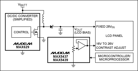
Figure 1. Simplified LCD contrast control circuit with buffer features the MAX5437/MAX5439 digital pots.
In Figure 1 the pot's 128 taps are distributed between ground and +26V with a LSB step of 0.2V.
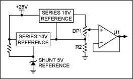
Figure 2. This design also features the MAX5437/MAX5439 digital pots, but here the voltage is independent of the pot's end-to-end resistance and tolerance.
In Figure 2 the MAX5437/MAX5439 applies 10V across the pot. Notice that the voltage is ratiometric; it is independent of the pot's end-to-end resistance and tolerance. By using a MAX5437 (50kΩ ±25%) or the MAX5439 (100kΩ ±25%), the current is changed but not the LSB voltage. The pot's 128 taps are distributed between +15V and +25V with a LSB step of 0.079V.
The MAX5439 is recommended for this design because it wastes less current. R2 puts the bottom series reference in the known condition to source a small amount of current.
If the 28V supply is regulated well enough for the application, the shunt and bottom series reference can be removed to save cost. The pot then floats 10V below +28V, with R2 passing the small current from the series reference and the pot.
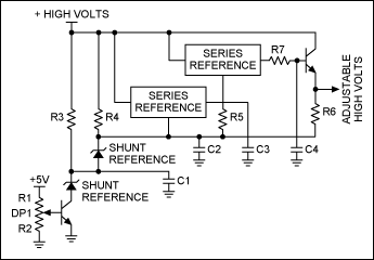
Figure 3. The high voltage applied is limited by the sum of the stacked references.
In this design R1 and R2 set a voltage across the pot between ground to 5V. The NPN and PNP transistors tend to cancel each other's temperature drift. R7 and C4 form a lowpass filter. Resistors 3 to 6 control currents; C1 to C3 are decoupling. Watch the power sequencing to insure that no component's maximum voltage is exceeded during power-up and power-down.
Maxim's complete list of digital pots and voltage references is available on the website.
打开APP阅读更多精彩内容
Introduction
There are ways to create a 30V adjustable voltage from a digital potentiometer that is limited to a 5V power-supply range. The easiest methods use a member of the MAX5436 digital pot family. Featuring digital logic-control voltages, which are independent of the pot voltages, these digital pots can withstand more than plus or minus 30V.This application note discusses how to reduce step voltage, increase accuracy, and improve temperature performance with a digital pot. A circuit using any digital pot without the special MAX5436 high-voltage capability is shown. This allows existing digital pots with up to 1024 taps to produce a voltage higher than their original specified power-supply voltage.
The Easy Way
Figure 1 shows a simple way to create a 30V adjustable voltage. The control voltages (2.7V to 5V) of the MAX5436–MAX5439 digital pots are independent of the pot voltages (+10V to +30V and -28V to -10V. or ±5V to ±15V).Figure 1. Simplified LCD contrast control circuit with buffer features the MAX5437/MAX5439 digital pots.
In Figure 1 the pot's 128 taps are distributed between ground and +26V with a LSB step of 0.2V.
Alternate Design Reduces Step Size
There is a design that will reduce the step size. See Figure 2.Figure 2. This design also features the MAX5437/MAX5439 digital pots, but here the voltage is independent of the pot's end-to-end resistance and tolerance.
In Figure 2 the MAX5437/MAX5439 applies 10V across the pot. Notice that the voltage is ratiometric; it is independent of the pot's end-to-end resistance and tolerance. By using a MAX5437 (50kΩ ±25%) or the MAX5439 (100kΩ ±25%), the current is changed but not the LSB voltage. The pot's 128 taps are distributed between +15V and +25V with a LSB step of 0.079V.
The MAX5439 is recommended for this design because it wastes less current. R2 puts the bottom series reference in the known condition to source a small amount of current.
If the 28V supply is regulated well enough for the application, the shunt and bottom series reference can be removed to save cost. The pot then floats 10V below +28V, with R2 passing the small current from the series reference and the pot.
Stack Multiple Series and Shunt References for Adjustable High Voltages
The approach in Figure 3 stacks two series and two shunt references to enable even higher adjustable voltages.Figure 3. The high voltage applied is limited by the sum of the stacked references.
In this design R1 and R2 set a voltage across the pot between ground to 5V. The NPN and PNP transistors tend to cancel each other's temperature drift. R7 and C4 form a lowpass filter. Resistors 3 to 6 control currents; C1 to C3 are decoupling. Watch the power sequencing to insure that no component's maximum voltage is exceeded during power-up and power-down.
Maxim's complete list of digital pots and voltage references is available on the website.
声明:本文内容及配图由入驻作者撰写或者入驻合作网站授权转载。文章观点仅代表作者本人,不代表电子发烧友网立场。文章及其配图仅供工程师学习之用,如有内容侵权或者其他违规问题,请联系本站处理。
举报投诉
-
什么是stack?2023-02-27 1554
-
#硬声创作季 02-NO STACK 解析醉 2022-10-26
-
Programming Tricks for Higher Conversion Speeds Utilizing De2010-06-01 692
-
Using References to Generate O2010-06-02 583
-
m5stack-esp原理图pdf资料下载2018-04-14 2046
-
基于V19N1-03-References电压参考的参考设计2021-06-26 270
-
级联与STACK与IRF与集群间的相互区别2021-08-31 557
-
stack-ide基于Stack的IDE后端JSON接口2022-06-13 295
-
配备M5Stack的智能工厂2022-12-09 268
-
带Blynk的M5Stack2022-12-19 281
-
使用Lumerical STACK求解器设计抗反射圆偏振器2023-04-15 783
-
重磅新品|CM4Stack2023-04-14 469
-
M5Stack圣诞雪球开源分享2023-06-28 187
-
StickC M5Stack LED闪烁2023-06-29 162
-
超级可爱的Stack酱机器人两岁啦2023-07-08 553
全部0条评论

快来发表一下你的评论吧 !
