

数据复用器添加光标移动到MAX7219或MAX7221的LE
液晶电视
1人已加入
描述
Abstract: The MAX7219 or MAX7221 7-segment LED display driver can highlight any one digit of its 8 digit display by adding a data multiplexer. This circuit intensifies the brightness of the selected digit to provide a cursor function for data entry as well as readout.
A data multiplexer (IC2) enables the LED-display driver in Figure 1 to highlight any selected digit by intensifying its brightness. This cursor function enables use of the display for data entry as well as readout.
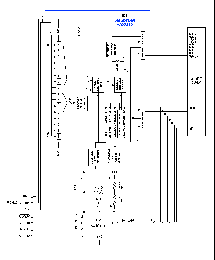
Figure 1. The digital multiplexer in this 8-digit display (IC2) provides a cursor function that intensifies the selected digit.
The operator of an environmental chamber, for instance, can set a desired temperature by entering that value via the display. Four "buttons" are required, but are not shown: left/right for selecting the digit to be intensified, and up/down for changing the digit's value (the buttons can be read by a microcontroller). Driving active-low CURSOR high then removes the cursor effect (by disabling IC2), and allows the display to continue monitoring temperature as it moves toward the new set point.
IC1 controls as many as eight 7-segment digits (eight segments including the decimal point) by scanning them sequentially and producing a value for each according to data stored in the chip via its serial interface. Each segment-driver output is a current source that delivers approximately 100 times the current entering ISET (pin 18). Thus, you can change the brightness of a given digit by altering the ISET current as that digit is scanned. (IC1 also provides a 16-level digital brightness control via 4-bit pulse-width modulation of the segment currents.)
The corresponding segments in each digit are bused together externally. The cathodes of all LED segments in a digit are bused together internally, allowing the digit to be turned on by drawing current from its common node with a logic-zero signal. Unselected digit-driver lines remain high. The digit-scan rate is approximately 1300/second.
When you apply a 3-bit digit-select code to IC2 while driving active-low CURSOR low, the multiplexer connects the corresponding digit signal to terminal Y and its complement to terminal W (pin 6). Thus, selecting a particular digit for cursor intensification drives W high during that digit scan, placing R1 and R3 in parallel and driving more current into ISET. (When W is low, R3 robs current from ISET.) If active-low CURSOR remains high, the digits exhibit uniform maximum brightness because W remains high for all of them.
Each of IC1's eight digit-driver outputs can sink LED currents as high as 320mA, but these outputs remain logic-compatible with the digital inputs of IC2. Even at 320mA, the digit-driver output voltages remain below the multiplexer's guaranteed low-level input voltage (VIL).
A related idea appeared in the 3/30/95 issue of EDN.
打开APP阅读更多精彩内容
A data multiplexer (IC2) enables the LED-display driver in Figure 1 to highlight any selected digit by intensifying its brightness. This cursor function enables use of the display for data entry as well as readout.
Figure 1. The digital multiplexer in this 8-digit display (IC2) provides a cursor function that intensifies the selected digit.
The operator of an environmental chamber, for instance, can set a desired temperature by entering that value via the display. Four "buttons" are required, but are not shown: left/right for selecting the digit to be intensified, and up/down for changing the digit's value (the buttons can be read by a microcontroller). Driving active-low CURSOR high then removes the cursor effect (by disabling IC2), and allows the display to continue monitoring temperature as it moves toward the new set point.
IC1 controls as many as eight 7-segment digits (eight segments including the decimal point) by scanning them sequentially and producing a value for each according to data stored in the chip via its serial interface. Each segment-driver output is a current source that delivers approximately 100 times the current entering ISET (pin 18). Thus, you can change the brightness of a given digit by altering the ISET current as that digit is scanned. (IC1 also provides a 16-level digital brightness control via 4-bit pulse-width modulation of the segment currents.)
The corresponding segments in each digit are bused together externally. The cathodes of all LED segments in a digit are bused together internally, allowing the digit to be turned on by drawing current from its common node with a logic-zero signal. Unselected digit-driver lines remain high. The digit-scan rate is approximately 1300/second.
When you apply a 3-bit digit-select code to IC2 while driving active-low CURSOR low, the multiplexer connects the corresponding digit signal to terminal Y and its complement to terminal W (pin 6). Thus, selecting a particular digit for cursor intensification drives W high during that digit scan, placing R1 and R3 in parallel and driving more current into ISET. (When W is low, R3 robs current from ISET.) If active-low CURSOR remains high, the digits exhibit uniform maximum brightness because W remains high for all of them.
Each of IC1's eight digit-driver outputs can sink LED currents as high as 320mA, but these outputs remain logic-compatible with the digital inputs of IC2. Even at 320mA, the digit-driver output voltages remain below the multiplexer's guaranteed low-level input voltage (VIL).
A related idea appeared in the 3/30/95 issue of EDN.
声明:本文内容及配图由入驻作者撰写或者入驻合作网站授权转载。文章观点仅代表作者本人,不代表电子发烧友网立场。文章及其配图仅供工程师学习之用,如有内容侵权或者其他违规问题,请联系本站处理。
举报投诉
- 相关推荐
- MAX7219
-
基于SPI的MAX7221与MCU是如何连接的?2021-05-25 0
-
MAX7219是什么2021-07-13 0
-
MAX7219是什么?如何去操作?2021-07-16 0
-
Max7221动态显示实验目的与步骤2021-12-13 0
-
max7219 MAX7221中文资料pdf2008-02-29 4055
-
使用电脑进行实验的MAX7219和MAX7221LED显示驱2009-04-27 1597
-
使用MAX7219/7221向更高电压或电流-Using t2009-04-27 1528
-
Migrating from the MAX7219 and2009-04-27 659
-
MAX7219和MAX7221串行接口8位LED显示驱动器的数据手册免费下载2019-12-03 960
-
MAX7219和MAX7221串行接口LED显示驱动器的数据手册免费下载2020-05-12 871
-
MAX7219/MAX7221英文手册2021-04-07 828
-
使用MAX7219/7221驱动更高的电压或电流2023-06-08 1380
-
从MAX7219和MAX7221迁移到MAX6950和MAX6951 LED驱动器2023-06-08 933
-
数据复用器将光标添加到MAX7219或MAX7221 LED 7段显示驱动器2023-06-08 562
-
使用PC试验MAX7219和MAX7221 LED显示驱动器2023-06-09 852
全部0条评论

快来发表一下你的评论吧 !
