

Battery Considerations for Tod
电源新闻
19人已加入
描述
This application note is courtesy of Lou Adams from Tadiran Batteries, Port Washington, NY.
Industrial/Military -40°C to +85°C (-40°F to +185°F)
Automotive -40°C to +115°C (-40°F to +239°F)
Geophysical - Down Hole 0°C to + 150°C (32°F to +302°F)
There are of course times when something wider may be required but these are the general categories.
Minimum Voltage 3.0V
Maximum Voltage 4.0V
Power Requirements, 3µA continuous
600µA for 150msec during read
Reads can be programmed from 1 per minute to 1 every 255 minutes.
First lest calculate the maximum power requirements.
Since the units are so small lets put them in terms of years.
3µA = 0.003 mA × 24 (hrs/day) × 365 (days/yr) = 26.28mAh/Year
Worst-case pulse load
60 (minutes) × 24 (hours) × 365 (days) = 525,600 minutes per year
525,600 × 150msec = 78,840 Seconds on load
78,840 ÷ 60 (seconds) ÷ 60 (minutes) = 21.9 hours
21.9 hours × 0.6 mA = 13.14mAh
The total power required to operate for 1 year is 13.14 + 26.28 = 39.42mAh. The average drain rate is 17.52 (mAh) ÷ 8760 (hours in year) = 0.0045 mA or 4.5µA. To this number we must add the self-discharge of the battery; this figure is provided by the battery manufacturer and based on both load and temperature.
Using Figure 1 we can see under an average drain of 4 1/2µA the cell (TL-5186) should yield 310mAh (The difference between the 400mAh cell rating and 310mAh can be attributed to self discharge) battery life = 310 / 4 1/2µA = 68,889 hours or 7.86 years.
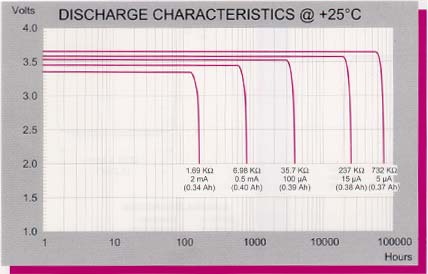
Figure 1. TL-5186 discharge characteristics.
See Figure 2 to check for load voltage over temperature for the above application no problems are found. See Figure 3 for capacity over temperature, we can see that at 72°C the capacity would be 280mAh and at -30, 330mAh. Since our average temperature works out to 25°C we go back to the 310 capacity and find an estimated battery life of 7 + years.
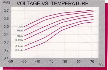
Figure 2. TL-5186 voltage vs temperature.
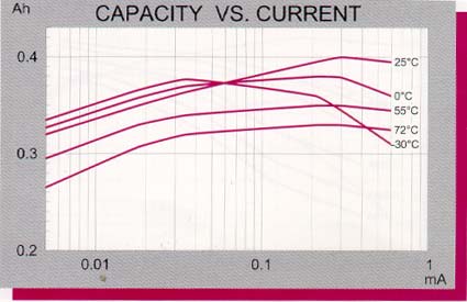
Figure 3. TL-5186 capacity vs current.
If for some reason we needed a little more life but just did not have room for a larger cell we could look at a series of specially designed low self-discharge designs. For this size cell we would look at the TL-4986
See Figure 4 from this discharge curve at 5µA we could see that 370mAh capacity should be expected. If we were to use this cell we could expect an average life of 9.38 years.
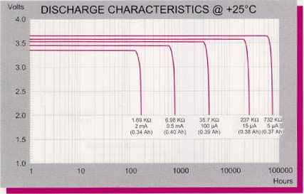
Figure 4. TL-5186 dishcarge characteristics.
The above application illustrates a fairly straight forward one as would be found for memory back up or back up of a real time clock.
打开APP阅读更多精彩内容
Temperature Range
Your battery must work over the temperature range of the finished device. Although this seems obvious many times we see a consumer type device trying to make it in an industrial or military environment.Typical Temperature Ranges
Consumer -20°C to +60°C (-4°F to + 140°F)Industrial/Military -40°C to +85°C (-40°F to +185°F)
Automotive -40°C to +115°C (-40°F to +239°F)
Geophysical - Down Hole 0°C to + 150°C (32°F to +302°F)
There are of course times when something wider may be required but these are the general categories.
Capacity
How to Figure Capacity Needed
In the battery world capacity is usually figured in Amp hours or milliamp hours, since we are dealing with low power devices we will use mAh (milliamp hours) This rating is dependant on the drain rate, voltage required, operating temperature and self discharge of the battery. Battery catalogs typically list the most advantageous ratings just like automotive mile per gallon ratings for your automobile. For lithium batteries intended for low to moderate rate applications the capacity would be shown for a 1,000-hour discharge. So if you come across a 1,000mAh cell you may assume the rating is for a 1 mA resistive discharge. As your drain rate increases your capacity will decrease due to the inefficiency of the discharge and as your load decreases your capacity will decrease due to self-discharge of the cell. Battery manufacturers provide curves to deal with these considerations.Voltage Considerations
Minimum Voltage
What is the lowest voltage your device will operate at? Many battery types show an unrealistic end of life voltage when figuring capacity. Make sure you understand the number used. An example would be the common every day alkaline cell, the nominal voltage is 1.5 volts but to achieve rated capacity you will need to operate down to 0.8 volts.Nominal Voltage
This is what the manufacturer puts on the label and through general usage can become confusing, especially when dealing with battery packs that contain cells in series. A good example would be the relatively new Lithium Battery area where the general assumption is that the cells are 3.0 volts, however, the reality is cells come in voltages from 2.8 to 3.9 volts with a few specials getting down to 1.5 volts per cell.Dealing With Pulses
Both the minimum voltage during the pulse and the effect on overall battery lifetime should be considered when looking at the pulse. Knowing the impedance of the cell, which varies over the life of the cell and also with the temperature is required to judge the voltage drop in the cell. To further complicate matters the internal reactions that result from the pulse can overtime have negative effects on battery life. The use of a parallel capacitor can greatly increase performance and battery life. As with the other parameters if you stay in the center of the batteries capability drain wise you should have no problems, however as you get to the higher drain rates the battery manufacturer should be consulted for recommendations.Mechanical Considerations
Internal Construction Techniques
Typically batteries are broken down into bobbin which are of limited surface area construction and spiral which have multiple surfaces for increased surface area.- Bobbin - consist of one interface between anode and cathode typically in lithium cells the outer circumference of the cell. By limiting the surface area you also limit the self-discharge of the cell. This also limits the ability to deliver high currents, which if you are building something for an intrinsically safe application would be an advantage. These cells are typically intended for light to moderate drain rates.
- Spiral - By taking the cathode/anode interface and wrapping it around a mandrill you achieve a larger surface area which in turn allows higher drain rates. This is necessary for high drain applications as would be found in military transceivers. The other side of the story is when you have this high rate capability you must take steps to limit the current to prevent the system from destroying itself should it be accidentally short circuited.
Battery Holders
While required for devices that require frequent battery changes, they insert their own set of reliability problems into the battery selection process. Things to consider would be strength of material over time to maintain constant pressure on the battery terminals; many holders now come with covers, which help in this area. In low drain applications consider if the low currents are sufficient to keep contacts in condition to pass these low currents.Connectors
This can be a good compromise where either marketing considerations or available board space make the use of a soldered in battery not feasible.Soldered In
From a reliability stand point as well as initial cost this should be the first choice. Why go through the trouble of carefully calculating the proper battery for 10 year or greater life and then compromising on the connection method.Typical Application
For practical uses, lets go through some typical applications.Low power data logger
Temp. Range -40°C to +85°CMinimum Voltage 3.0V
Maximum Voltage 4.0V
Power Requirements, 3µA continuous
600µA for 150msec during read
Reads can be programmed from 1 per minute to 1 every 255 minutes.
First lest calculate the maximum power requirements.
Since the units are so small lets put them in terms of years.
3µA = 0.003 mA × 24 (hrs/day) × 365 (days/yr) = 26.28mAh/Year
Worst-case pulse load
60 (minutes) × 24 (hours) × 365 (days) = 525,600 minutes per year
525,600 × 150msec = 78,840 Seconds on load
78,840 ÷ 60 (seconds) ÷ 60 (minutes) = 21.9 hours
21.9 hours × 0.6 mA = 13.14mAh
The total power required to operate for 1 year is 13.14 + 26.28 = 39.42mAh. The average drain rate is 17.52 (mAh) ÷ 8760 (hours in year) = 0.0045 mA or 4.5µA. To this number we must add the self-discharge of the battery; this figure is provided by the battery manufacturer and based on both load and temperature.
Using Figure 1 we can see under an average drain of 4 1/2µA the cell (TL-5186) should yield 310mAh (The difference between the 400mAh cell rating and 310mAh can be attributed to self discharge) battery life = 310 / 4 1/2µA = 68,889 hours or 7.86 years.
Figure 1. TL-5186 discharge characteristics.
Other Considerations to Cover
Load Voltage and Capacity Over TemperatureSee Figure 2 to check for load voltage over temperature for the above application no problems are found. See Figure 3 for capacity over temperature, we can see that at 72°C the capacity would be 280mAh and at -30, 330mAh. Since our average temperature works out to 25°C we go back to the 310 capacity and find an estimated battery life of 7 + years.
Figure 2. TL-5186 voltage vs temperature.
Figure 3. TL-5186 capacity vs current.
If for some reason we needed a little more life but just did not have room for a larger cell we could look at a series of specially designed low self-discharge designs. For this size cell we would look at the TL-4986
See Figure 4 from this discharge curve at 5µA we could see that 370mAh capacity should be expected. If we were to use this cell we could expect an average life of 9.38 years.
Figure 4. TL-5186 dishcarge characteristics.
The above application illustrates a fairly straight forward one as would be found for memory back up or back up of a real time clock.
声明:本文内容及配图由入驻作者撰写或者入驻合作网站授权转载。文章观点仅代表作者本人,不代表电子发烧友网立场。文章及其配图仅供工程师学习之用,如有内容侵权或者其他违规问题,请联系本站处理。
举报投诉
- 相关推荐
- Battery
-
LI FE Battery study!!!!2015-06-29 0
-
Battery spec!!!!!!!!!!2015-06-29 0
-
如何使用Battery Historian分析电源使用情况2021-12-29 0
-
ESD/Latch-Up Considerations wi2009-06-21 416
-
Battery charger and method of2009-11-28 502
-
Thermal Considerations2009-11-29 700
-
Security Considerations for Vo2010-04-27 390
-
最新TOD文本显示中文画面组态软件2010-11-29 1017
-
Design Considerations for Dall2009-03-31 866
-
Battery Charger Indicates Tric2009-04-30 2241
-
Using Dallas Battery Managemen2009-04-30 786
-
Ni-MH Battery2009-11-21 2754
-
Important considerations for i2010-05-14 802
-
无线电接收机Design Considerations for Direct2016-12-16 394
-
TOD、BOD和COD的含义及其区别的分析2017-09-21 1664
全部0条评论

快来发表一下你的评论吧 !
