

MAX2170 S11 Data for VHF and L-Band Input
通信设计应用
58人已加入
描述
|
MAX2170 S11 Data for VHF and L-Band Input
Abstract: This application note shows how the MAX2170 triple-band (T-DMB, DAB, FM) receiver's input-scattering parameter (S11) is measured for the VHF and L-band inputs. OverviewThe MAX2170 direct conversion to low-IF tuner has an input scattering parameter (S11), which is measured for the VHF and L-band inputs. The calibration plane is at the pin of the IC.The VHF input consists of a bandpass tracking filter followed by an LNA. The return loss will be good for the desired channel, but will look reflective for the out-of-band channels. As a result, the S11 data will change significantly as the MAX2170 tunes to a new channel. To address this issue, the series 91nH inductor, which is part of the VHF tracking filter, was removed from the input for the S11 measurements (Figure 1). Removing this component changes the tracking filter's shape but allows S11 calibration to the pin of the IC. Note, however, that the 91nH inductor is required for the tracking filter to operate properly. It must be used in the final application. The L-band input consists of ESD diodes and an LNA. The input will look resistive with some shunt capacitance. The S11 data for this input will not vary when the MAX2170 tunes to a new channel. The L-band input can be modeled as a resistor R = 23.4Ω in series with C = 4.2pF. 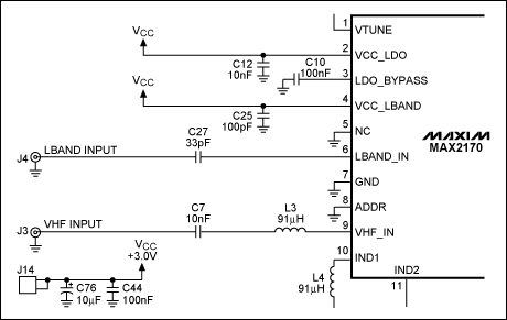 Figure 1. Schematic of the VHF and L-band inputs to the MAX2170. The 91nH inductor for the VHF input can be removed for calibration of S11 data. Performance SummaryTable 1 shows S11 data (magnitude and phase) for the VHF and L-band inputs. The RF frequency is changed for each measurement.Table 1. S11 (Magnitude/Phase) for VHF and L-Band Input
Table 2 shows S11 data (real and imaginary) for the VHF and L-band inputs. The RF frequency is changed for each measurement. Table 2. S11 (Real/Imaginary) for VHF and L-Band Inputs
Test Results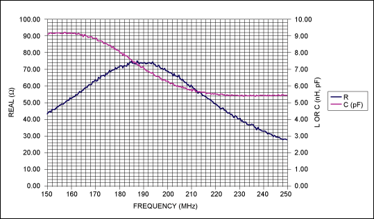 Figure 2. The Thevenin equivalent resistance and capacitance for the VHF input when the RF is tuned to 174.928MHz. 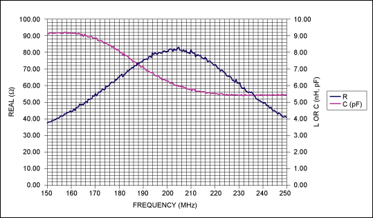 Figure 3. The Thevenin equivalent resistance and capacitance for the VHF input when the RF is tuned to 204.64MHz. 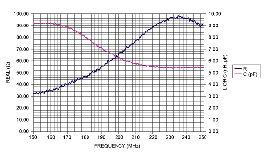 Figure 4. The Thevenin equivalent resistance and capacitance for the VHF input when the RF is tuned to 239.2MHz. 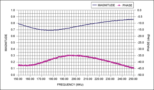 Figure 5. S11 magnitude and phase for the VHF input with the MAX2170 tuned to 174.928MHz. Note that this s-parameter data will change if the MAX2170's RF frequency changes. 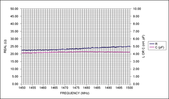 Figure 6. The Thevenin equivalent resistance and capacitance for the L-band input. The Thevenin equivalent circuit looks the same for RF frequencies from 1450MHz to 1500MHz. The average value is R = 23.4Ω in series with C = 4.2pF. 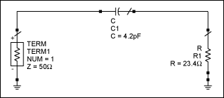 Figure 7. The Thevenin model of L-band RF input in a 50Ω system 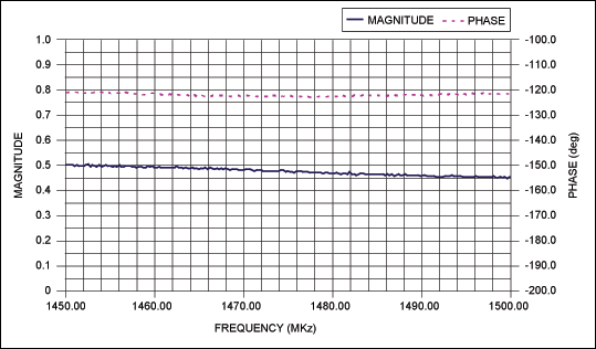 Figure 8. S11 magnitude and phase for the L-band input. Test FilesThe following test files contain S11 data in CITIFILE format for the MAX2170.
|
||||||||||||||||||||||||||||||||||||||||||||||||||||||||||||||||||||||||||||||||
声明:本文内容及配图由入驻作者撰写或者入驻合作网站授权转载。文章观点仅代表作者本人,不代表电子发烧友网立场。文章及其配图仅供工程师学习之用,如有内容侵权或者其他违规问题,请联系本站处理。
举报投诉
-
没有S参数测试装置的S11测量2018-12-10 0
-
校准前S11读-7dB对吗?2018-12-27 0
-
SOLT与不同的s11和s22为2端口cal2019-02-14 0
-
S11参数以及功率的测量2019-04-17 0
-
三频段RF调谐器MAX2170资料推荐2021-04-19 0
-
S11的带宽是什么意思?是系统工作带宽吗?2021-06-25 0
-
MAX2170/MAX2171 DAB/T-DMB参考设计2008-08-19 1494
-
MAX2170, MAX2171 直接变频至低IF的调谐器,2009-01-22 678
-
MAX2170 VHF和L波段输入端口的S11参数2009-09-18 1869
-
MAX2170,MAX2171直接变频至低IF的调谐器用于数字音频广播2009-09-18 976
-
VHF 和 L 波段输入的 MAX2170 S11 数据2022-11-18 86
-
MAX2170 S11数据用于VHF和L波段输入2023-01-10 642
-
MAX2170/MAX2171 DAB/T-DMB数字无线电调谐器2023-01-10 887
全部0条评论

快来发表一下你的评论吧 !

