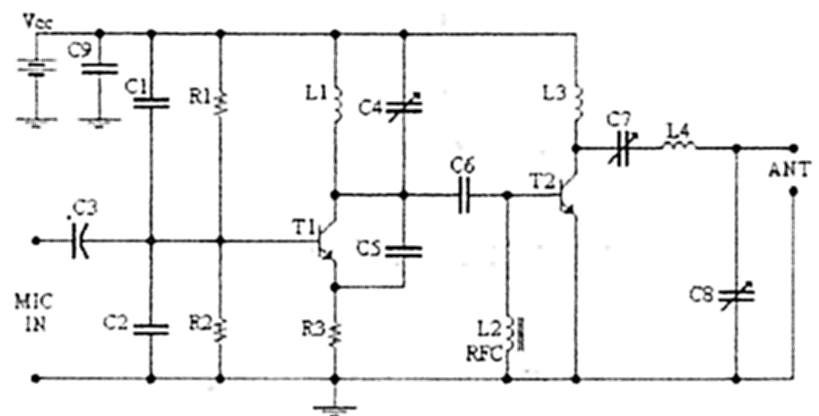

4W调频发射电路图
无线通信电子电路图
描述
4W调频发射电路图
TECHNICAL CHARACTERISTICS:
Stabilised tendency of catering: Vcc=12~16V
Frequency of emission: 88~108MHzConsumption: 100~400mAMaterially:
The resistors are 1/4W.
R1, R2
10KOhm
R3
47Ohm
C1, C2
1nF
C3
4,7uF/16V
C4, C7, C8
0~45pF trimmer
C5, C6
10pF
C9
100nF
L1
4 turns, 7mm diameter *
L3
3 turns, 7mm diameter *
L4
5 turns, 7mm diameter *
L2
RFC (resistance 1MOhm with wrapped around her inductor of enough coils from fine isolated wire. Scratch of utmost inductor and you stick in utmost the resistance making thus a parallel L-r circuit.)
T1, T2
2N2219
ANT
Simple dipole l/2.
MIC IN
Microphone dynamic or other type. (It can also connected to a cassette player unit)
* The inductors is air from wire of coaxial 75W or other 1mm roughly.
Regulations:
With the C4 we regulate the frequency.
With their C7, C8 we adapt the resistance of aerial (practically to them we regulate so that it is heard our voice in the radio as long as you become cleaner).
Notes:
The T2 wants refrigerator.
-
 源边居士
2011-10-05
0 回复 举报谢谢提供好东西 收起回复
- 相关推荐
- 发射电路
-
业余调频发射电路集萃2011-10-13 0
-
MC2833P调频发射电路图2009-03-16 1483
-
调频发射器电路图2008-10-18 0
-
多种电路图2012-11-15 0
-
小型调频发射电路及制作2009-04-13 1330
-
BH1417调频立体声发射电路图2007-06-26 1666
-
88-108MHz调频发射电路(FM发射电路)2007-06-26 3529
-
单声道调频发射电路2008-10-18 1041
-
光发射电路图2008-12-21 991
-
MC2833P调频发射电路2009-03-15 1728
-
调频对讲机发射电路图2009-03-16 3009
-
96Mhz调频发射电路图2009-04-10 1614
-
调频发射电路2011-06-30 2342
-
单片集成的小型调频发射电路图2014-07-28 3126
-
发射功率高达4W的调频发射电路分享2022-07-05 2545
全部0条评论

快来发表一下你的评论吧 !


