

AM Transmitter
无线通信电子电路图
描述
AM Transmitter
Notes:
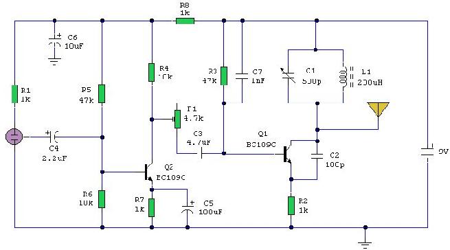
Please read the disclaimer on this site before making any transmitter circuit. It is illegal to operate a radio transmitter without a license in most countries. This ircuit is deliberately limited in power output but will provide amplitude modulation (AM) of voice over the medium wave band.
The circuit is in two halfs, an audio amplifier and an RF oscillator. The oscillator is built around Q1 and associated components. The tank circuit L1 and VC1 is tunable from about 500kHz to 1600KHz. These components can be used from an old MW radio, if available. Q1 needs regenerative feedback to oscillate and this is achieved by connecting the base and collector of Q1 to opposite ends of the tank circuit. The 1nF capacitor C7, couples signals from the base to the top of L1, and C2, 100pF ensures that the oscillation is passed from collector, to the emitter, and via the internal base emitter resistance of the transistor, back to the base again. Resistor R2 has an important role in this circuit. It ensures that the oscillation will not be shunted to ground via the very low internal emitter resistance, re of Q1, and also increases the input impedance so that the modulation signal will not be shunted. Oscillation frequency is adjusted with VC1.
Q2 is wired as a common emitter amplifier, C5 decoupling the emitter resistor and realising full gain of this stage. The microphone is an electret condenser mic and the amount of AM modulation is adjusted with the 4.7k preset resistor P1.
An antenna is not needed, but 30cm of wire may be used at the collector to increase transmitter range.
- 相关推荐
- transmitte
-
SPDIF Transmitter控制器用户手册2022-10-09 0
-
Gowin SPDIF Transmitter IP用户指南2022-10-09 0
-
Transmitter Reference Design f2008-08-18 929
-
Medium range transmitter2009-12-22 1094
-
FM跟踪发射器FM Tracking Transmitter2009-12-22 2397
-
Crosby direct FM transmitter b2009-12-22 1954
-
Stereo FM transmitter block di2009-12-22 1465
-
PLL FM Transmitter block diagr2009-12-22 1772
-
FM Transmitter2009-12-22 1878
-
Surveillance Transmitter Detec2009-12-22 1127
-
FM Transmitter Circuit2009-12-22 1461
-
激光发射器/接收器电路 LASER Transmitter/2010-02-05 5467
-
Alarm Sounds When RF Transmitter is Out of Range2011-08-25 1172
-
CAT-AM74-AM74K AMPOWER 刀闸分断2021-07-09 91
-
CAT-AM74-AM74 AMPOWER 端子无螺钉孔2021-07-09 402
全部0条评论

快来发表一下你的评论吧 !
