

浅析基于verilog如何实现PWM DAC
描述
PWM 采用任意宽度的输入值,并创建只有一位宽度的输出。使用自由运行计数器的 PWM,这是能做的最简单的 PWM。
module PWM( input clk, input rst_n, input [3:0] PWM_in, output PWM_out);
reg [3:0] cnt;always @(posedge clk or negedge rst_n) if(!rst_n) cnt《=0; else cnt 《= cnt + 1‘b1; // free-running counter
assign PWM_out = (PWM_in 》 cnt)?1’b1:1‘b0; // comparatorendmodule
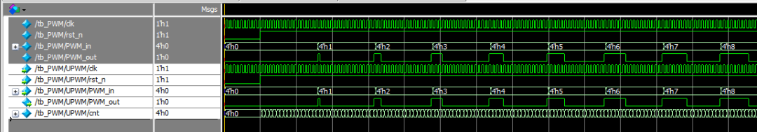
选择了一个4位的 PWM 这里,所以 PWM 周期是16。输入可以从0到15,因此 PWM 输出比从0% 到15/16 = 93% 。如果需要能够达到100% ,输入需要有一个额外的bit位。
这段代码工作得很好,尽管当前形式的代码有点幼稚,因为输入必须是固定的(或者只有当计数器溢出 = 返回到0时才会更改)。否则输出将出现故障。因此,很可能需要一些额外的逻辑(通常是在正确的时间捕获输入的闩锁)
使用可加载的上下计数器的 PWM,这是一个稍微复杂一点的设计。
module PWM2( input clk, input rst_n, input [3:0] PWM_in, output PWM_out);
reg [3:0] cnt;reg cnt_dir; // 0 to count up, 1 to count downwire [3:0] cnt_next = cnt_dir ? cnt-1’b1 : cnt+1‘b1;wire cnt_end = cnt_dir ? cnt==4’b0000 : cnt==4‘b1111;
always @(posedge clk or negedge rst_n ) if(!rst_n) cnt 《= 0; else cnt 《= cnt_end ? PWM_in : cnt_next;always @(posedge clk or negedge rst_n) if(!rst_n) cnt_dir《=1’b0; else cnt_dir 《= cnt_dir ^ cnt_end;assign PWM_out = cnt_dir;endmodule
它使用一个可加载的上下计数器,不需要输出比较器。有趣的是,它并不完全等同于第一个设计,因为输出周期有17个状态而不是16个(输出从1/17 = 6% 到16/17 = 94%)。
编辑:jq
-
基于至简设计法实现的PWM调制verilog2017-09-27 0
-
浅析STM32的PWM和DAC的练习2021-08-17 0
-
怎么实现基于STM32的PWM和DAC的功能?2021-11-19 0
-
一种基于PWM的电压输出DAC电路设计2016-01-14 948
-
PWM DAC文档2016-05-03 579
-
FPGA设计中DAC控制的Verilog实现图文稿2021-07-26 700
-
FPGA设计中DAC控制的Verilog实现2021-07-26 830
-
FPGA设计中DAC控制的Verilog实现修订稿2021-07-26 523
-
使用PWM实现DAC2021-09-17 768
-
PWM模拟DAC的关键参数分析2021-09-17 688
-
一种基于PWM的电压输出DAC电路设计.2021-09-17 877
-
PWM DAC相关资料2021-09-18 610
-
STM的PWM与DAC学习2021-11-23 483
-
PWM DAC2021-12-16 542
全部0条评论

快来发表一下你的评论吧 !
