

使用Verilog/SystemVerilog硬件描述语言练习数字硬件设计
描述
HDLBits 是一组小型电路设计习题集,使用 Verilog/SystemVerilog 硬件描述语言 (HDL) 练习数字硬件设计~
网址如下:
https://hdlbits.01xz.net/
关于HDLBits的Verilog实现可以查看下面专栏:
https://www.zhihu.com/column/c_1131528588117385216
缩略词索引:
SV:SystemVerilog
Problem 15-Vector3
题目说明
模块 32 位输入向量如下所示,按照上下对应关系,输出为下方的 4 个 8-bits 向量。
 图片来自 HDLBits
这个题目的核心就是上面的图片,将上面的输入向量映射到下面向量。
模块端口声明
module top_module (
    input [4:0] a, b, c, d, e, f,
    output [7:0] w, x, y, z );
题目解析
这个题目重点是向量拼接,拼接操作符的基本语法使用 { } 将较小的向量括起来,每个 { } 内的向量使用逗号作为间隔。
{3'b111, 3'b000} => 6'b111000
{1'b1, 1'b0, 3'b101} => 5'b10101
{4'ha, 4'd10} => 8'b10101010     // 4'ha and 4'd10 are both 4'b1010 in binary
拼接运算符中的向量务必需要标注位宽,不然综合器怎么能知道你的结果需要多宽的位宽。因此 { 1,2,3 } 这样的操作是非法的,并会产生一个 Error:unsized constants are not allowed in concatenations.
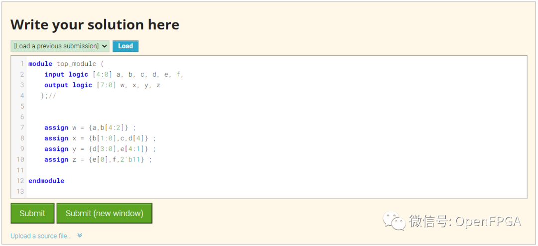
module top_module (
    input logic [4:0] a, b, c, d, e, f,
    output logic [7:0] w, x, y, z
   );//


    assign w = {a,b[4:2]} ;
    assign x = {b[1:0],c,d[4]} ;
    assign y = {d[3:0],e[4:1]} ;
    assign z = {e[0],f,2'b11} ;
endmodule
点击Submit,等待一会就能看到下图结果:
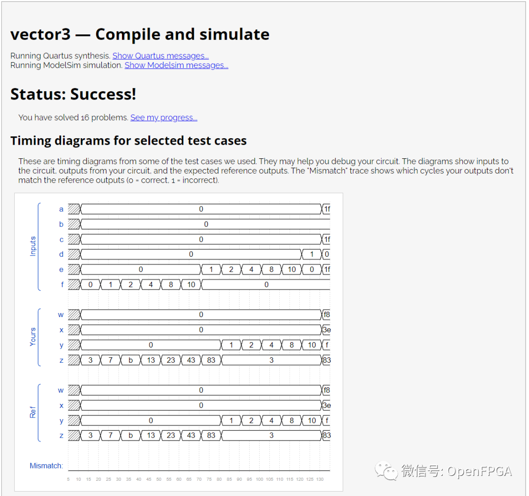
注意图中的Ref是参考波形,Yours是你的代码生成的波形,网站会对比这两个波形,一旦这两者不匹配,仿真结果会变红(后面会展示)。
这一题就结束了。
Problem 16-Vectorr
题目说明
给定一个 8bit 输入向量,将其反向输出。
模块端口声明
module top_module(
    input [7:0] in,
    output [7:0] out
);
题目解析
这道题难度不大但是不要想着使用assign out[7:0] = in[0:7];解决问题,因为在Verilog中这个语句不起作用,因为Verilog使用向量时的位序应与定义时保持一致。
简单解决就是将输入按照一个一个bit分开,然后重新组合即可。
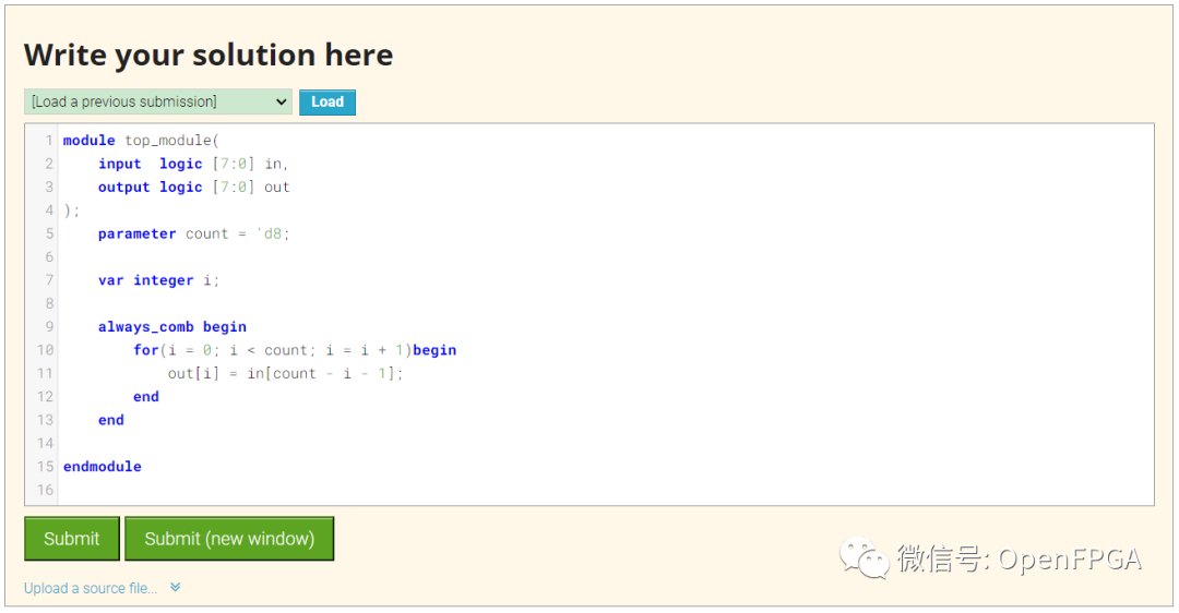
但是如果向量是1024位呢?大家可以思考,后续还有类似问题,再使用其他方式解决,下面有参考示例。
简单解答
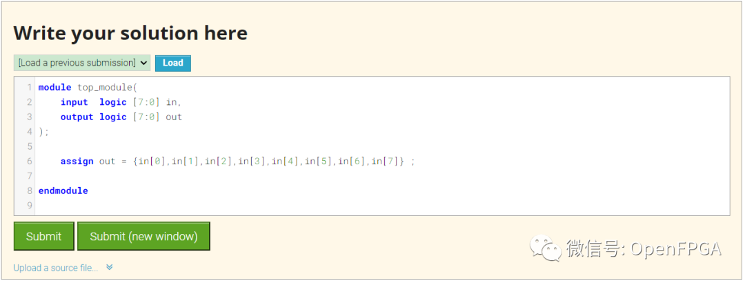
module top_module(
    input  logic [7:0] in,
    output logic [7:0] out
);

    assign out = {in[0],in[1],in[2],in[3],in[4],in[5],in[6],in[7]} ;

endmodule
其他方式解决
module top_module(
    input  logic [7:0] in,
    output logic [7:0] out
);
    parameter count = 'd8;

    var integer i;

    always_comb begin
        for(i = 0; i < count; i = i + 1)begin
            out[i] = in[count - i - 1];
        end
    end

endmodule
点击Submit,等待一会就能看到下图结果:
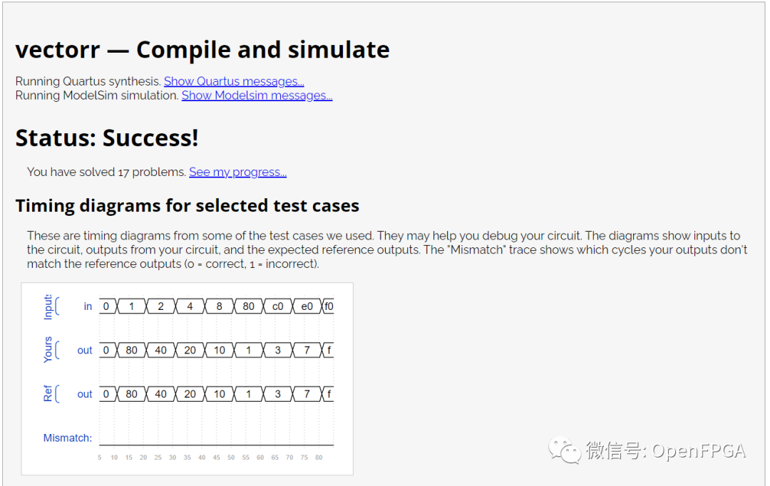
注意图中的Ref是参考波形,Yours是你的代码生成的波形,网站会对比这两个波形,一旦这两者不匹配,仿真结果会变红(后面会展示)。
这一题就结束了。
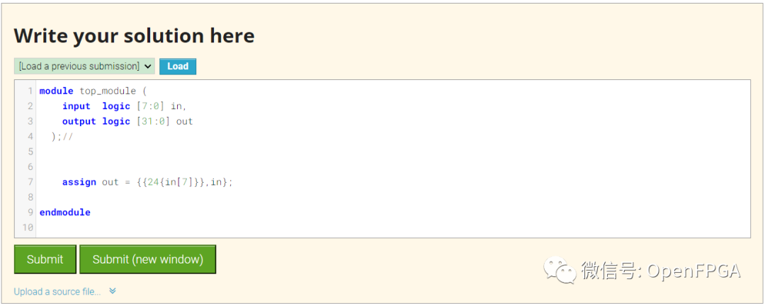
Problem 17-Vector4
题目说明
将一个 8bit 有符号数扩展为 32bit 数。
模块端口声明
module top_module (
    input [7:0] in,
    output [31:0] out );
题目解析
本题考查的是向量的复制和拼接语法:{ 重复次数 { 向量 } }。
重复次数必须是一个常量,而且请特别注意重复操作符有两对 { }.外层的 {} 不能少。
如:
{5{1'b1}}           // 5'b11111 (or 5'd31 or 5'h1f)
{2{a,b,c}}          // The same as {a,b,c,a,b,c}
{3'd5, {2{3'd6}}}   // 9'b101_110_110. It's a concatenation of 101 with
                    // the second vector, which is two copies of 3'b110.
还需要注意有符号和无符号的复制:
重复操作符的应用场景之一是在有符号数的扩展。有符号数的扩展是将符号位填充待扩展的比特。比如要将 4bit 的 4'b0101 有符号数扩展为 8bit ,0 是符号位,那么扩展之后为 8'b0000 0101.
module top_module (
    input  logic [7:0] in,
    output logic [31:0] out
  );//


    assign out = {{24{in[7]}},in};

endmodule
点击Submit,等待一会就能看到下图结果:
注意图中是没有波形的~
这一题就结束了。
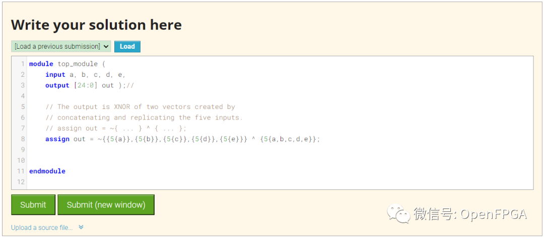
Problem 18-Vector5
题目说明
给定五个 1 位信号(a、b、c、d 和 e),计算 25 位输出向量中的所有 25 个成对的逻辑比较。如果被比较的两位相等,则输出应为 1。
 图片来自 HDLBits
问题的核心就是上面的图片,相关操作如下:
out[24] = ~a ^ a;   // a == a, so out[24] is always 1.
out[23] = ~a ^ b;
out[22] = ~a ^ c;
...
out[ 1] = ~e ^ d;
out[ 0] = ~e ^ e;
模块端口声明
module top_module (
    input a, b, c, d, e,
    output [24:0] out );
题目解析
这个题目还是上一题的延续,属于将几个知识点串联起来,向量复制扩展,XNOR操作,前面知识掌握了这个题目就不难了。
module top_module (
    input a, b, c, d, e,
    output [24:0] out );//

    // The output is XNOR of two vectors created by
    // concatenating and replicating the five inputs.
    // assign out = ~{ ... } ^ { ... };
    assign out = ~{{5{a}},{5{b}},{5{c}},{5{d}},{5{e}}} ^ {5{a,b,c,d,e}};


endmodule
点击Submit,等待一会就能看到下图结果:
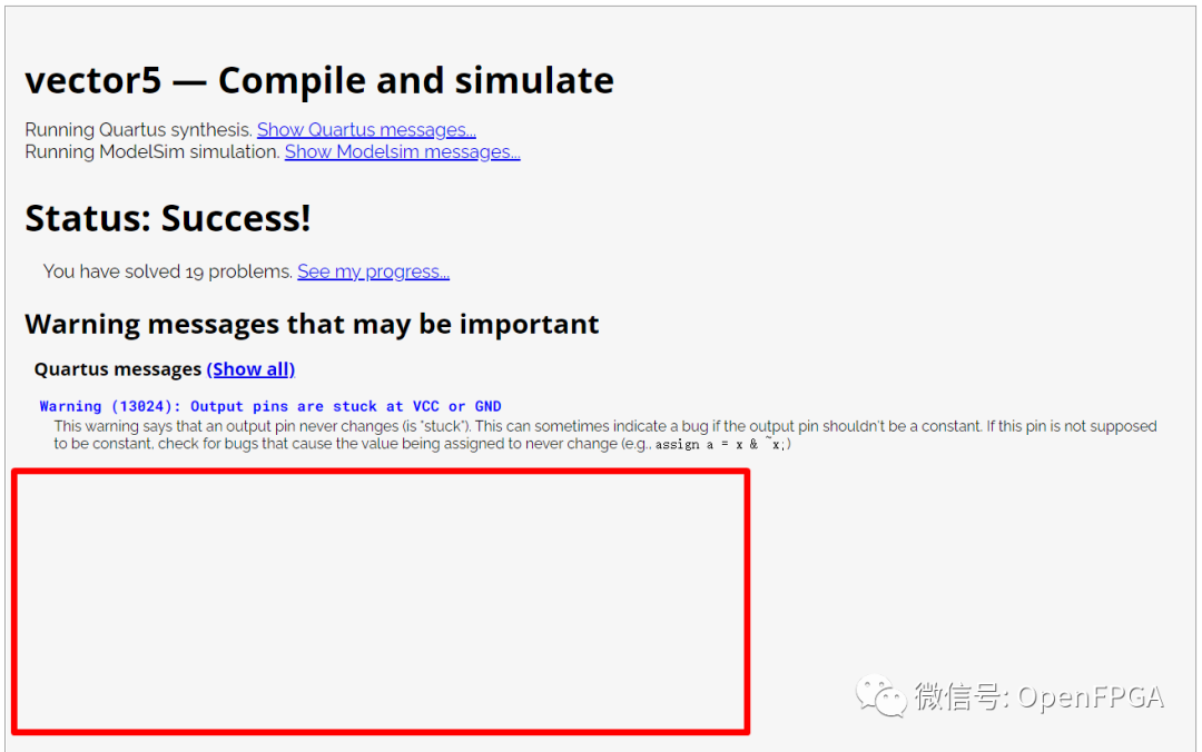
注意图中无波形~
这一题就结束了。
总结
今天的几道题就结束了,整体难度不大,后面的题目难度会越来越大~
最后我这边做题的代码也是个人理解使用,有错误欢迎大家批评指正,祝大家学习愉快~
-
Verilog HDL硬件描述语言2013-01-13 0
-
Verilog_HDL硬件描述语言2013-02-26 0
-
verilog+hdl硬件描述语言2013-08-12 0
-
Verilog硬件描述语言描述.2006-03-27 1297
-
VERILOG HDL硬件描述语言2009-07-20 690
-
Verilog HDL硬件描述语言【书籍2010-07-02 629
-
verilog硬件描述语言课程讲义2012-05-21 792
-
Verilog硬件描述语言参考手册2015-11-12 636
-
Verilog硬件描述语言2016-09-01 664
-
基于Verilog硬件描述语言的IEEE标准硬件描述语言资料合集免费下载2020-06-18 707
-
Verilog硬件描述语言的学习课件免费下载2021-01-22 718
-
使用Verilog/SystemVerilog硬件描述语言练习数字硬件设计2022-09-08 1248
全部0条评论

快来发表一下你的评论吧 !
