

自制遥控机械臂的教程
描述
一种机械臂,可通过带有传感器的手套无线模拟您的手部运动。
它由带有柔性传感器的手套控制的人造手组成。人工手通过控制手套无线再现手的动作。手和手套都适用于 Arduino。
第 1 步:所需材料
控制手套的材料:
•弹性手套;
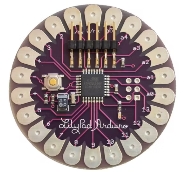
• LilyPad Arduino板(有不同的版本,通常只有 4 个模拟输入,所以请注意并购买图片中的那个):它的工作原理与经典的 Arduino UNO 完全一样,或者您甚至可以直接使用 Arduino Nano;
• XBee 模块:用于无线电通信;
•屏蔽连接Xbee模块;
• 5 个弯曲传感器;
• 5 个电阻器:47 KΩ ;
•带3x1.5 V电池的电池组(Lilypad 可以从2.7 到5.5 V 供电,所以4.5 V 就可以了);
• LilyPad FTDI 适配器:将 LilyPad 板连接到 PC 并使用 Arduino IDE 加载程序(非常可选,因为您也可以使用 Arduino UNO 板移除 ATmega 芯片,但每次都进行这种连接很棘手) 。
机械臂的材料:
•手掌为钢结构,手指为木结构;
• Arduino UNO板;
• XBee 模块;
• 5 个伺服电机5V 供电(我使用 TowerPro SG90);
• Arduino UNO 的伺服电机护罩:连接伺服电机我使用了FuturaElettronica的 Robot_Shield,它还有一个开关稳压器为整个电路供电,但您可以使用任何用于控制伺服电机的护罩。链接:https://store.open-electronics.org/index.php?_rou.。. ;
•连接XBee模块的屏蔽(我做了一个可怕的,但它很经济,我需要做一个小因为Robot_Shield 的大小);
•钓鱼线;
•(可选)钓鱼坠子,用于固定钓鱼线,也可以简单地打一个结;
• 9 伏电池。
- 所需工具:
•角磨机(主要用于切割木材和钢材);
•轴向磨床;
•焊机(带电极);
•钻孔;
•焊台和焊锡;
• 电工剪刀;
•钳子;
•热缩管。
第2步:制作手套
为了制作控制手套,我建议首先选择不同组件的正确位置,然后用适当长度的电线连接所有东西。
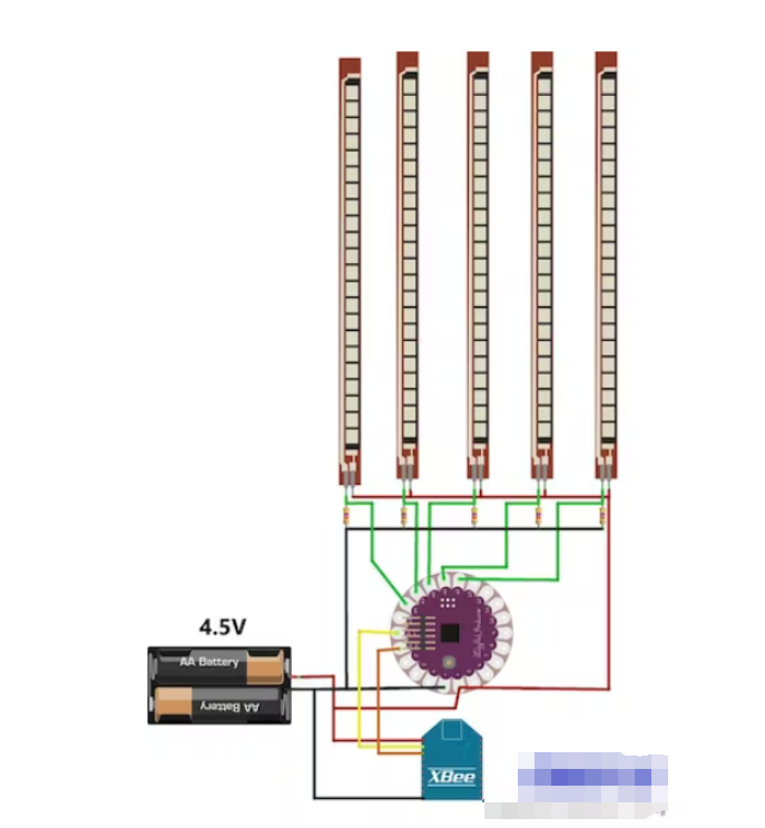
要使用 Arduino LilyPad 进行模拟读取,您需要制作一个分压器,因为柔性传感器不像电位器那样工作(它们只有 2 个触点)。
所以按照方案,首先将 5 个电阻焊接在 LilyPad 板上,一侧连接到 5 个不同的模拟引脚,另一侧共同接地。然后焊接柔性传感器,一侧连接到 5 个不同的模拟引脚,另一侧连接到正极。
然后连接 XBee Shield:两根线用于电源,另外两根用于信号。将 Tx 引脚焊接到 Rx,反之亦然。
现在你需要电池组和手套了。
注意:不要为 Arduino LilyPad 供电超过 5.5 V,也不要反过来供电
第 3 步:制作机械臂
这是最复杂的部分,因为您必须选择合适的材料来制作手部,但如果您有可能 3D 打印手部,这也很容易(网上有许多不同的 3D 项目用于打印手部部件)。
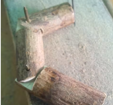
我开始用软木制作手指,为动作找到合适的结构,然后用树枝制作。
因此,每根手指制作三个木制圆柱体,其中两个比你的指骨的正常长度长 1 厘米,需要将一个部件放入另一个部件中。
然后用角磨机制作凹槽以使零件装配在一起(参见图片,您会更好地理解)。
你需要一些砂纸使碎片弯曲,以便它们可以旋转。
用钻头为铰链打孔,然后你必须为钓鱼线打另外两个孔,垂直方向,一个朝向手内侧,一个向外。因此,当电线设置在手指的顶部时,向内拉时手指会闭合,向外拉时手指会打开。
但我后面发现手掌是有问题的,因为我最初是用木头做的,而较薄的部分总是会断裂。所以我决定用钢制造它,这一次我没有遇到任何问题。
剪下它并做一些类似于手指的突起,将它们固定在手掌上(参见图片作为参考)。然后用钻头为钓鱼线制作其他孔,拇指会很棘手,因为它不像其他手指那样垂直。
动手后,您需要为五个伺服电机和 Arduino UNO 板做一个支撑。一定要选择舵机的正确位置,这样它们在旋转时不会相互接触。
最后一部分是将手指连接到伺服电机:将钓鱼线固定在手指顶部并使其穿过孔;然后,当电线位于手的底部时,以最大旋转 (180°) 转动转子(手动,不通电),使其处于垂直位置,然后将闭合手指的电线设置到最低转子的孔,例如打结;再次将转子旋转 0°(它再次垂直,之前打的结在顶部),然后将另一根线(打开手指)设置到转子的最低孔。按照此步骤中的最后一张图片更好地理解。
因此,当电机处于 0°(垂直)时,手指打开,而当转子处于 180°(再次垂直)时,手指关闭。
第 4 步:机械臂的电路
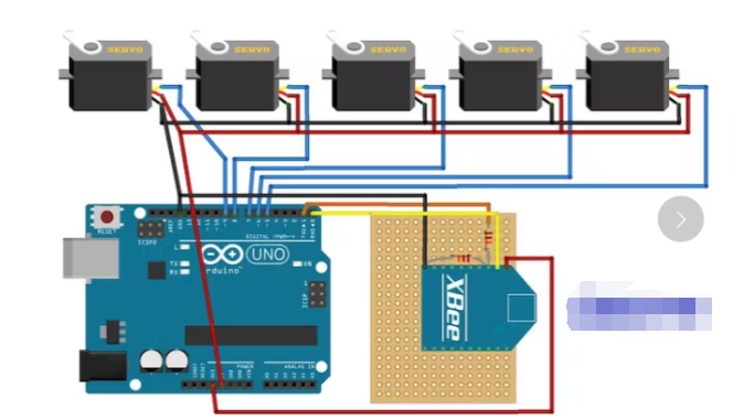
对于电路,您可以选择使用带有 XBee 护罩的 Arduino UNO 伺服电机护罩,或者使用 XBee 模块和引脚制作定制护罩用于伺服电机,并通过其插孔端口为 Arduino UNO 供电。
我制作的 DIY XBee Shield 使用 12 KOhm 电阻和 22 KOhm 电阻,您可以在图片中看到接线。
所以我使用了我之前已经购买的东西,但是你可以使用任何让你控制伺服电机和 XBee 的东西。
伺服电机有 3 根电线:
黄色:信号(连接到数字引脚);
红色:电源(+5 V);
棕色:接地(GND)。
我使用了最简单的伺服电机,工作电压为 5 V,旋转角度为 180 度(这是完美的角度,我们不需要更多)。
电脑的USB接口无法提供足够的电源来控制5个伺服电机,所以我建议使用12V电源测试一切,然后使用9V电池(碱性电池为佳)。
第 5 步:程序
记住:要加载程序,您必须删除连接到 Arduino 的 TX 和 RX 引脚的所有东西(在本例中是 XBee 模块),否则程序将无法加载。还要记住在 IDE(LilyPad 或 Arduino UNO)中设置正确类型的 Arduino。
两个代码的链接:
https://codebender.cc/sketch:59559
https://codebender.cc/sketch:55013
试试这个代码来测试手套上的弹性传感器:https ://codebender.cc/sketch:56264
这是为了测试 Lilypad 和 Arduino Uno 之间的连接:https ://codebender.cc/sketch:55014
Untitled file:
/*
Flex Glove
Created by Santin Gabriele, 2014
I.T.S.T. "J. F. Kennedy", cl. 5^A EA
Thanks to Elias De Lamper for suggestions to improve this program!
*/
int ResThumb = A4; // Variables of the analog read form the flex sensors connected to the analog pins of Arduino LilyPad
int ResIndex = A3;
int ResMiddle = A2;
int ResAnnular = A1;
int ResPinky = A0;
int OpenedThumb =0; // Variables of the values when the hand is completely opened
int OpenedIndex =0; // This is needed for a continuous calibration
int OpenedMiddle =0;
int OpenedAnnular =0;
int OpenedPinky =0;
int ClosedThumb; // Variables of the values when the hand is completely closed
int ClosedIndex; // We can't set it to zero since that the minimum value reached
int ClosedMiddle; // in the analog read never reach zero. We'll assign the value of
int ClosedAnnular; // a first analog read, then the program in the loop will
int ClosedPinky; // automatically assing lower values
int thumb =0; // Variables of the values to send
int index =0;
int middle =0;
int annular =0;
int pinky =0;
void setup()
{
Serial.begin(9600); // Activating serial communication, XBee Series 1 are pre-programmed at 9600 baud/s
pinMode(ResThumb, INPUT); // The variables of the sensor are set as input
pinMode(ResIndex, INPUT);
pinMode(ResMiddle, INPUT);
pinMode(ResAnnular, INPUT);
pinMode(ResPinky, INPUT);
ClosedThumb = analogRead(ResThumb);
ClosedIndex = analogRead(ResIndex);
ClosedMiddle = analogRead(ResMiddle);
ClosedAnnular = analogRead(ResAnnular);
ClosedPinky = analogRead(ResPinky);
}
void loop()
{
thumb = analogRead(ResThumb);
index = analogRead(ResIndex);
middle = analogRead(ResMiddle);
annular = analogRead(ResAnnular);
pinky = analogRead(ResPinky);
if(thumb > OpenedThumb) // Calibration reading and setting the maximum values. This needs you to completely open your hand a few times
OpenedThumb = thumb;
if(index > OpenedIndex)
OpenedIndex = index;
if(middle > OpenedMiddle)
OpenedMiddle = middle;
if(annular > OpenedAnnular)
OpenedAnnular = annular;
if(pinky > OpenedPinky)
OpenedPinky = pinky;
if(thumb < ClosedThumb) // Calibration reading and setting the minimum values. This needs you to completely close your hand a few times
ClosedThumb = thumb;
if(index < ClosedIndex)
ClosedIndex = index;
if(middle < ClosedMiddle)
ClosedMiddle = middle;
if(annular < ClosedAnnular)
ClosedAnnular = annular;
if(pinky < ClosedPinky)
ClosedPinky = pinky;
thumb = map(thumb ,ClosedThumb ,OpenedThumb ,0,180); // The analog read has to be readapted in values between 0 and 180 to be used by the servomotors.
index = map(index ,ClosedIndex ,OpenedIndex ,0,180); // The minimum and maximum values from the calibrations are used to correctly set the analog reads.
middle = map(middle ,ClosedMiddle ,OpenedMiddle ,0,180);
annular = map(annular,ClosedAnnular,OpenedAnnular,0,180);
pinky = map(pinky ,ClosedPinky ,OpenedPinky ,0,180);
Serial.write("<"); // This character represent the beginning of the package of the five values
Serial.write(thumb); // The values are sent via the Tx pin (the digital pin 1)
Serial.write(index);
Serial.write(middle);
Serial.write(annular);
Serial.write(pinky);
delay(30);
}
-
自制PC遥控器2011-12-27 10715
-
DIY:自制遥控万色返空蛋2017-01-12 503
-
舵机怎么调机械臂2016-07-30 0
-
想做一个底盘加机械臂的移动机械臂,有感兴趣的或者给点建议的朋友吗?2017-04-26 0
-
#开箱体验#开源机械臂开箱2017-07-17 0
-
机械臂问题2018-01-18 0
-
关于机械臂的设计问题2019-12-16 0
-
机械臂仿真控制2020-09-29 0
-
【资料推荐】基于Arduino的PS2机械臂遥控小车(L298N)傻瓜教程2021-06-29 0
-
华为天才少年稚晖君自制机械臂,能给葡萄缝针的那种,成本 1 万块2021-10-11 0
-
怎么实现基于Arduino的PS2机械臂遥控小车的设计?2021-10-19 0
-
工业机械臂的相关资料推荐2021-11-29 0
-
机械臂的相关资料分享2022-01-20 0
-
机械臂的控制学习2022-02-23 0
-
红外遥控器DIY自制2011-12-22 23279
全部0条评论

快来发表一下你的评论吧 !
