

STM32时钟系统详解
控制/MCU
描述
1. STM32的时钟源主要有:
内部时钟
外部时钟
锁相环倍频输出时钟
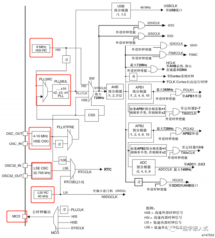
1.1 详细介绍
HSI(内部高速时钟)
它是RC振荡器,频率可以达到8MHZ,可作为系统时钟和PLL锁相环的输入。
HSE(外部高速时钟)
接入晶振范围是4-16MHZ,可作为系统时钟和PLL锁相环的输入,还可以经过128分频之后输入给RTC。
LSI(内部低速时钟)
它是RC振荡器,频率大概为40KHZ,供给独立看门狗或者RTC,并且独立看门口只能依靠LSI作为时钟源。
LSE(外部低速时钟)
通常外接32.768MHZ晶振提供给RTC。
PLL(锁相环)
用来倍频输出。因为开发板外部晶振只有8MHZ,而STM32最大工作频率是72MHZ。他可以通过HSI输入,HSE输入或两分频输入,通过PLL倍频(2-16),倍频之后输入给系统时钟。
MCO(时钟输出管脚)
通常对应STM32 PA8,它可以选择一个时钟信号输出,给外部的系统提供时钟源。
2. 标准库的时钟配置
2.1 stm32启动文件
首先打开startup_stm32f10x_hd.s,该文件为stm32的启动文件,在该文件内会发现有这么一块用汇编写的代码。
      Reset_Handler   PROC
            EXPORT  Reset_Handler    [WEAK]
            IMPORT  __main
            IMPORT  SystemInit
            LDR     R0, =SystemInit
            BLX     R0
            LDR     R0, =__main
            BX      R0
            ENDP
通过这段汇编代码可以看出,程序在执行main函数之前,会先执行SystemInit函数。
2.2 SystemInit函数详解
void SystemInit (void)
{
  /* Reset the RCC clock configuration to the default reset state(for debug purpose) */
  /* Set HSION bit */
  RCC->CR |= (uint32_t)0x00000001;

  /* Reset SW, HPRE, PPRE1, PPRE2, ADCPRE and MCO bits */
#ifndef STM32F10X_CL
  RCC->CFGR &= (uint32_t)0xF8FF0000;
#else
  RCC->CFGR &= (uint32_t)0xF0FF0000;
#endif /* STM32F10X_CL */

  /* Reset HSEON, CSSON and PLLON bits */
  RCC->CR &= (uint32_t)0xFEF6FFFF;

  /* Reset HSEBYP bit */
  RCC->CR &= (uint32_t)0xFFFBFFFF;

  /* Reset PLLSRC, PLLXTPRE, PLLMUL and USBPRE/OTGFSPRE bits */
  RCC->CFGR &= (uint32_t)0xFF80FFFF;

#ifdef STM32F10X_CL
  /* Reset PLL2ON and PLL3ON bits */
  RCC->CR &= (uint32_t)0xEBFFFFFF;

  /* Disable all interrupts and clear pending bits  */
  RCC->CIR = 0x00FF0000;

  /* Reset CFGR2 register */
  RCC->CFGR2 = 0x00000000;
#elif defined (STM32F10X_LD_VL) || defined (STM32F10X_MD_VL) || (defined STM32F10X_HD_VL)
  /* Disable all interrupts and clear pending bits  */
  RCC->CIR = 0x009F0000;

  /* Reset CFGR2 register */
  RCC->CFGR2 = 0x00000000;
#else
  /* Disable all interrupts and clear pending bits  */
  RCC->CIR = 0x009F0000;
#endif /* STM32F10X_CL */

#if defined (STM32F10X_HD) || (defined STM32F10X_XL) || (defined STM32F10X_HD_VL)
  #ifdef DATA_IN_ExtSRAM
    SystemInit_ExtMemCtl();
  #endif /* DATA_IN_ExtSRAM */
#endif

  /* Configure the System clock frequency, HCLK, PCLK2 and PCLK1 prescalers */
  /* Configure the Flash Latency cycles and enable prefetch buffer */
  SetSysClock();

#ifdef VECT_TAB_SRAM
  SCB->VTOR = SRAM_BASE | VECT_TAB_OFFSET; /* Vector Table Relocation in Internal SRAM. */
#else
  SCB->VTOR = FLASH_BASE | VECT_TAB_OFFSET; /* Vector Table Relocation in Internal FLASH. */
#endif
}
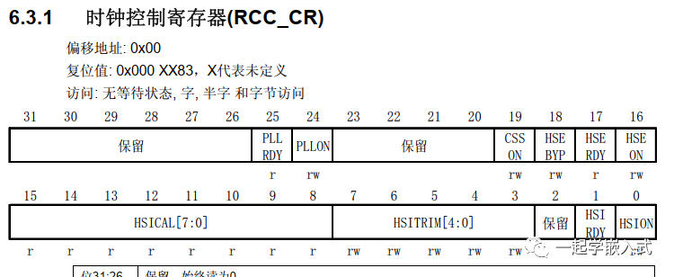
打开内部8M时钟
RCC->CR |= (uint32_t)0x00000001
通过查看寄存器手册可知,这段代码为打开内部8M时钟。
设置时钟配置寄存器
#ifndef STM32F10X_CL
  RCC->CFGR &= (uint32_t)0xF8FF0000;
#else
  RCC->CFGR &= (uint32_t)0xF0FF0000;
#endif /* STM32F10X_CL */
对应寄存器说明可查看《STM32中文参考手册_V10》的6.3.2 时钟配置寄存器(RCC_CFGR)章节。
后续代码,有兴趣可根据《STM32中文参考手册_V10》手册,查看代码具体作用。
2.3 SetSysClock()函数详解
static void SetSysClock(void)
{
#ifdef SYSCLK_FREQ_HSE
  SetSysClockToHSE();
#elif defined SYSCLK_FREQ_24MHz
  SetSysClockTo24();
#elif defined SYSCLK_FREQ_36MHz
  SetSysClockTo36();
#elif defined SYSCLK_FREQ_48MHz
  SetSysClockTo48();
#elif defined SYSCLK_FREQ_56MHz
  SetSysClockTo56();
#elif defined SYSCLK_FREQ_72MHz
  SetSysClockTo72();
#endif
}
system_stm32f10x.c文件中会根据芯片的型号定义对应的宏
#if defined (STM32F10X_LD_VL) || (defined STM32F10X_MD_VL) || (defined STM32F10X_HD_VL)
/* #define SYSCLK_FREQ_HSE    HSE_VALUE */
 #define SYSCLK_FREQ_24MHz  24000000
#else
/* #define SYSCLK_FREQ_HSE    HSE_VALUE */
/* #define SYSCLK_FREQ_24MHz  24000000 */
/* #define SYSCLK_FREQ_36MHz  36000000 */
/* #define SYSCLK_FREQ_48MHz  48000000 */
/* #define SYSCLK_FREQ_56MHz  56000000 */
#define SYSCLK_FREQ_72MHz  72000000
#endif
3. 时钟配置函数
3.1 时钟初始化配置函数
void SystemInit(void);
SYSCLK(系统时钟)=72MHZ;
AHB总线时钟(HCLK=SYSCLK)=72MHZ;
APB1总线时钟(PCLK1=SYSCLK/2)=36MHZ;
APB2总线时钟(PCLK1=SYSCLK/1)=72MHZ;
PLL主时钟=72MHZ;
3.2 外设时钟使能配置函数
void RCC_AHBPeriphClockCmd(uint32_t RCC_AHBPeriph, FunctionalState NewState);
void RCC_APB2PeriphClockCmd(uint32_t RCC_APB2Periph, FunctionalState NewState);
void RCC_APB1PeriphClockCmd(uint32_t RCC_APB1Periph, FunctionalState NewState);
3.3 时钟源使能函数
void RCC_HSICmd(FunctionalState NewState);
void RCC_LSICmd(FunctionalState NewState);
void RCC_PLLCmd(FunctionalState NewState);
void RCC_RTCCLKCmd(FunctionalState NewState);
3.4 时钟源和倍频因子配置函数
void RCC_HSEConfig(uint32_t RCC_HSE);
void RCC_SYSCLKConfig(uint32_t RCC_SYSCLKSource);
void RCC_HCLKConfig(uint32_t RCC_SYSCLK);
void RCC_PCLK1Config(uint32_t RCC_HCLK);
void RCC_PCLK2Config(uint32_t RCC_HCLK);
3.5 外设时钟复位函数
void RCC_APB2PeriphResetCmd(uint32_t RCC_APB2Periph, FunctionalState NewState);
void RCC_APB1PeriphResetCmd(uint32_t RCC_APB1Periph, FunctionalState NewState);
3.6 自定义系统时钟
void RCC_HSE_Config(u32 div,u32 pllm)
{
    RCC_DeInit();
    RCC_HSEConfig(RCC_HSE_ON);
    if(RCC_WaitForHSEStartUp()==SUCCESS)
    {
        RCC_HCLKConfig(RCC_SYSCLK_Div1);
        RCC_PCLK1Config(RCC_HCLK_Div2);
        RCC_PCLK2Config(RCC_HCLK_Div1);
        RCC_PLLConfig(div,pllm);
        RCC_PLLCmd(ENABLE);
    while(RCC_GetFlagStatus(RCC_FLAG_PLLRDY)==RESET)
        RCC_SYSCLKConfig(RCC_SYSCLKSource_PLLCLK)
    while(RCC_GetSCLKSource()!=0x08);

    }
}
审核编辑:汤梓红
-
浅析STM32系统时钟RCC2021-08-11 0
-
系统时钟RCC详解2021-08-12 0
-
详解STM32的时钟树时钟信号2021-08-19 0
-
STM32时钟树案例详解2021-08-20 0
-
STM32的时钟树详解2021-08-23 0
-
详解STM32时钟系统2021-11-05 0
-
STM32系统时钟框架图2016-08-18 1039
-
一图详解STM32单片机的5个时钟源资料下载2021-04-20 601
-
STM32最小系统和时钟详解2021-11-17 783
-
【STM32】STM32F4时钟系统2021-11-25 845
-
STM32系统时钟RCC详解2021-11-30 897
-
【自学笔记】STM32时钟系统详解2021-12-09 343
-
【STM32】系统时钟RCC详解(超详细,超全面)2021-12-14 538
-
2.STM32的存储器、电源和时钟体系2022-01-07 298
-
STM32时钟系统与时钟启动顺序详解2022-02-09 723
全部0条评论

快来发表一下你的评论吧 !
