

基于Linux使用spidev驱动OLED
嵌入式技术
描述
如果不想编写spi设备驱动,那么linux内核提供了一个通用的spidev设备驱动,提供统一的字符设备操作,那么只需要在应用层读写和控制即可。以SPI OLED为例子,使用spidev驱动OLED,基于linux5.15.
参考源码:
tools/spi/spidev_fdx.c
tools/spi/spidev_test.c
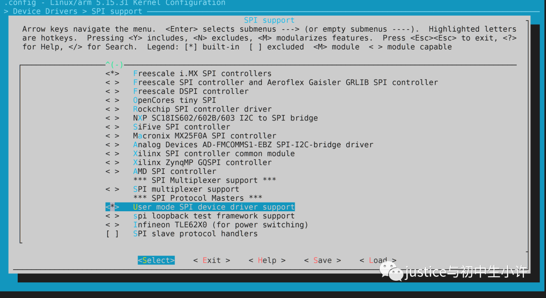
1.配置使能spidev用户态驱动
- > Device Drivers                                                                                         │
         - > SPI support
      < * >   User mode SPI device driver support
驱动源文件:driver/spi/spidev.c
2.编写设备树
&ecspi2{
 fsl,spi-num-chipselects = < 1 >;
 cs-gpios = < &gpio1 29 GPIO_ACTIVE_LOW >;//GPIO1_29
 pinctrl-names = "default";
 pinctrl-0 = < &pinctrl_ecspi2 >;
 status = "okay";

 oled: ssd13306@0{
  compatible = "Justice,ssd13306";//匹配spidev驱动
  spi-cpol;
  spi-cpha;
  spi-rx-bus-width = < 0 >;
  spi-max-frequency = < 20000000 >;
  reset-gpios = < &gpio1 27 GPIO_ACTIVE_LOW >;
  dc-gpios = < &gpio1 31 GPIO_ACTIVE_HIGH >;
  reg = < 0 >;
 };
};
注意这里的compatible 属性,在新版linux内核,可以写任意的字符串,最好不再写”spidev”,老版的是要写成”spidev”。给出的理由是: spidev should never be referenced in DT without a specific compatible string, it is a Linux implementation thing rather than a description of the hardware
3.修改spidev驱动,增加compatible
//driver/spi/spidev.c

static const struct of_device_id spidev_dt_ids[] = {
 { .compatible = "rohm,dh2228fv" },
 { .compatible = "lineartechnology,ltc2488" },
 { .compatible = "semtech,sx1301" },
 { .compatible = "lwn,bk4" },
 { .compatible = "dh,dhcom-board" },
 { .compatible = "menlo,m53cpld" },
 { .compatible = "cisco,spi-petra" },
 { .compatible = "micron,spi-authenta" },
 { .compatible = "Justice,ssd13306" },
 {},
};
在最后一行增加自己的匹配compatible。
4.用户态读写、控制spi设备
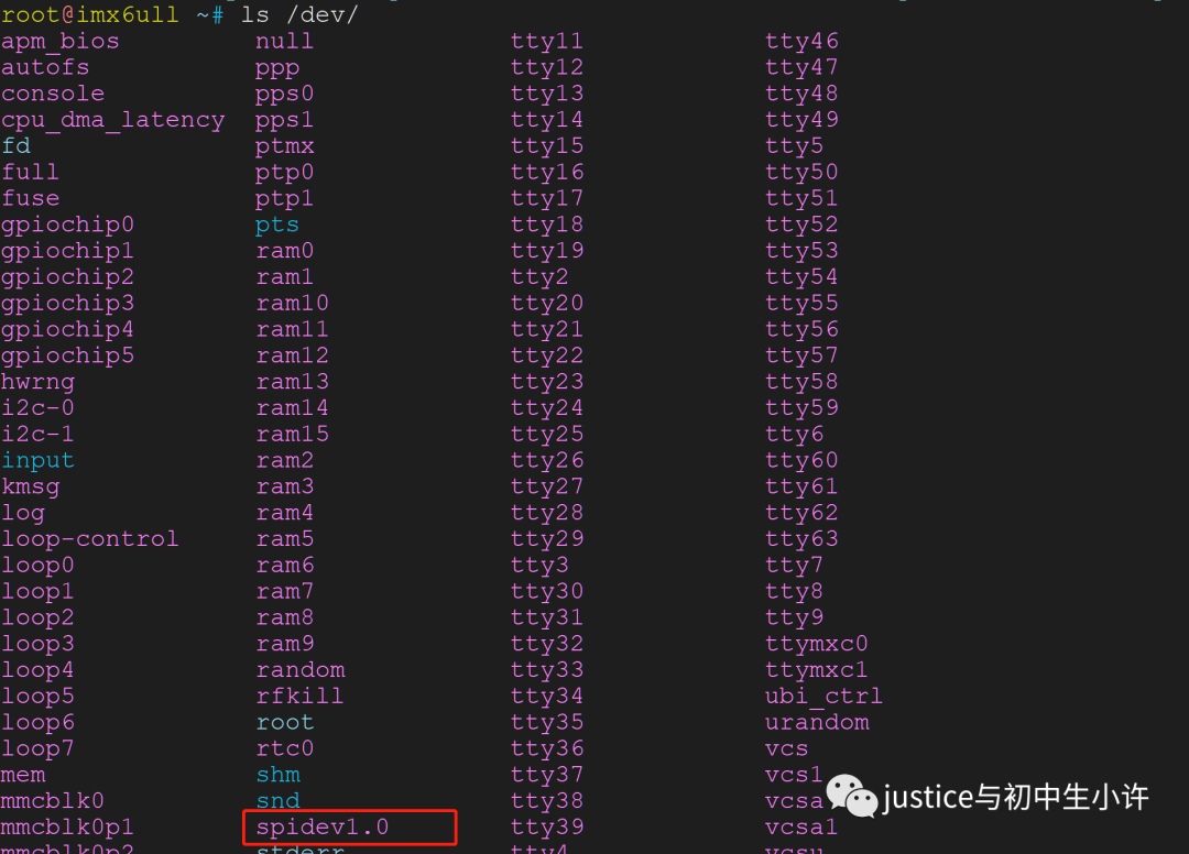
当设备树和spidev成功匹配后,就为我们的spi设备生成了一个设备节点/dev/spidevx.y。
x表示spi控制器的软件枚举的总线号,y表示这个spi控制器的片选号。
设备树aliases会影响spi控制器的软件枚举的总线号,如我使用ecspi2,芯片上spi控制器的第2个spi控制器,但是我的设备树上面写了aliases,因此我呈现的就是/dev/spidev1.0
aliases {
  ...
  spi0 = &ecspi1;
  spi1 = &ecspi2;
  spi2 = &ecspi3;
  spi3 = &ecspi4;
}
/sys/class/spidev下可以确认spidev枚举出了多少个spi设备
root@imx6ull /sys/class/spidev# ls
spidev1.0
设置传输模式
spi 核心会根据spi device的mode标志,来决定一些传输的模式,比如时钟极性、LSB等等
这个标志是32位,低16位是用户空间设置,高16位是内核控制,因此不能有冲突。如果在设置之前读取,读取到的模式和设备树定义的一样。
以下是用户空间的宏定义。
include/uapi/linux/spi/spi.h
#define SPI_CPHA  _BITUL(0) /* clock phase */
#define SPI_CPOL  _BITUL(1) /* clock polarity */

#define SPI_MODE_0  (0|0)  /* (original MicroWire) */
#define SPI_MODE_1  (0|SPI_CPHA)
#define SPI_MODE_2  (SPI_CPOL|0)
#define SPI_MODE_3  (SPI_CPOL|SPI_CPHA)
#define SPI_MODE_X_MASK  (SPI_CPOL|SPI_CPHA)

#define SPI_CS_HIGH  _BITUL(2) /* chipselect active high? */
#define SPI_LSB_FIRST  _BITUL(3) /* per-word bits-on-wire */
#define SPI_3WIRE  _BITUL(4) /* SI/SO signals shared */
#define SPI_LOOP  _BITUL(5) /* loopback mode */
#define SPI_NO_CS  _BITUL(6) /* 1 dev/bus, no chipselect */
#define SPI_READY  _BITUL(7) /* slave pulls low to pause */
#define SPI_TX_DUAL  _BITUL(8) /* transmit with 2 wires */
#define SPI_TX_QUAD  _BITUL(9) /* transmit with 4 wires */
#define SPI_RX_DUAL  _BITUL(10) /* receive with 2 wires */
#define SPI_RX_QUAD  _BITUL(11) /* receive with 4 wires */
#define SPI_CS_WORD  _BITUL(12) /* toggle cs after each word */
#define SPI_TX_OCTAL  _BITUL(13) /* transmit with 8 wires */
#define SPI_RX_OCTAL  _BITUL(14) /* receive with 8 wires */
#define SPI_3WIRE_HIZ  _BITUL(15) /* high impedance turnaround */

/*
 * All the bits defined above should be covered by SPI_MODE_USER_MASK.
 * The SPI_MODE_USER_MASK has the SPI_MODE_KERNEL_MASK counterpart in
 * 'include/linux/spi/spi.h'. The bits defined here are from bit 0 upwards
 * while in SPI_MODE_KERNEL_MASK they are from the other end downwards.
 * These bits must not overlap. A static assert check should make sure of that.
 * If adding extra bits, make sure to increase the bit index below as well.
 */
#define SPI_MODE_USER_MASK (_BITUL(16) - 1)