

幻彩灯珠的秘密
电子说
描述
幻彩灯珠介绍
一、幻彩灯珠其实我们可以理解为该灯珠内部有一颗LED驱动芯片外加R,G,B 3种颜色的LED的合封体。并且这颗LED驱动芯片可以驱动3路 LED,每一路LED驱动都跟内部的R,G,B通过封装打线连接好了。
1、幻彩灯珠的应用场所:
(1)、家庭照明。幻彩灯珠可以应用于家庭中的各种照明场景,如客厅、卧室、厨房等。多彩变幻的颜色可以为家庭营造出温馨、浪漫的氛围。
(2)、商业场所。幻彩灯珠可以应用于商业场所的装饰和照明,如商场、酒店、ktv等。多彩变幻的颜色可以为商业场所营造出艺术感和时尚感。
(3)、户外景观。幻彩灯珠可以应用于城市公园、广场、桥梁等户外景观,为城市增添艺术气息和夜间景观
2、幻彩灯珠对比传统灯珠优缺点:
(1)、颜色多彩变幻。幻彩灯珠的多彩变幻可以为家庭、商业场所等营造出良好的氛围
(2)、相比传统的三基色LED灯珠+外置LED驱动芯片体积要小,更容易生产
(3)、相比传统的LED灯珠+外置LED驱动芯片 成本更低
幻彩灯珠内置驱动芯片介绍
一、市场常见的有WS2812,SM16703P,目前我们公司推出了AD2203芯片,该芯片性价比更高。
AD2203是三通道LED驱动IC,内部集成有MCU数字接口、数据锁存器、LED驱动等电路。通过外围MCU控制实现该芯片的单独灰度、级联控制实现户外大屏的彩色点阵发光控制 。 主要特征: 默认上电灯不亮,恒流12mA(可定制),256级灰度可调,数据自动整形,传输数率800---1200KHz,标准应用电压5V
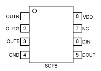 管脚定义
管脚定义 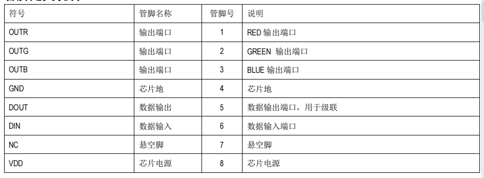
具体参数如下:
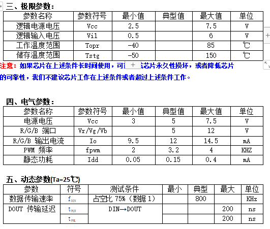
六、通讯方式和应用电路
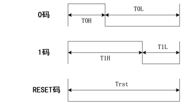
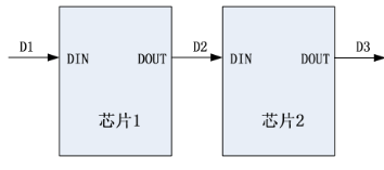
芯片设计为单线归零码通讯方式。芯片上电复位以后,接收DIN 的数据,足24 bit 后,DOUT 端口开始转发数据,输出到下一个芯片。在转发之前DOUT=0电位。芯片 OUTR、OUTG、OUTB 三个端口可输出相应24 bit 数据的不同占空比的信号。如果DIN 端输入信号为RESET 信号,芯片将接收到的数据送显示,芯片将在该信号结束后重新接收新的数据,在接收完开始的 24bit 数据后,通过DOUT口转发数据,芯片在没有接收到RESET 码前,OUTR、OUTG、OUTB 管脚原输出亮度保持不变,当接收到不小于80µs 低电平RESET 码后,芯片将刚才接收到的24 bit 亮度数据输出到OUTR、OUTG、OUTB 引脚上。 七、数据编码格式
T0H: 350ns T0L: 800ns T1H: 800ns T1L: 350ns (容错20%) Trst > 80us
八、级连方法
九、数据传输方法
单芯片24BIT数据发送顺序:高位先发,即R7先发送

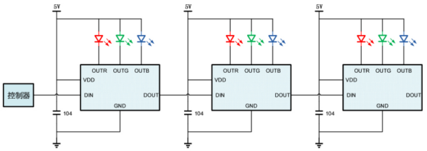
十、典型应用电路
AD2202 应用编程之炫彩渐变效果(MCU 应广150C)
#include "extern.h"
byte red, green, blue; //Could save these three bytes by using the rgb EWORD directly ( rgb$0, rgb$1, rgb$2)
byte mode;
byte hueinc;
byte firstinc;
EWORD rgb;
word pixels; //Only has to be a word if number of pixels > 255
word firstPixelHue;
#define definedPIXELS 300;//像素点
bit LED : pa.6;
bit BTN : pa.4;
int count;
//====================bit1
send1 MACRO
SET1 LED;
.DELAY 5;
$ LED low;
// .DELAY 1; //Going around is enough delay
ENDM
//===================bit0
send0 MACRO
SET1 LED;
.DELAY 2;
$ LED low;
.DELAY 2;
ENDM
//========================
void SendRGB (void)
{
DISGINT; //Let's not get interrupted
.FOR bitno, <23,22,21,20,19,18,17,16,15,14,13,12,11,10,9,8,7,6,5,4,3,2,1,0> //Regular for() loop doesn't work, but at least the compiler can do the hard work
if (rgb.bitno == 0)
{
send0;
}
else
{
send1;
}
.ENDM
ENGINT;
}
void show (void) {
rgb$0 = blue; //I lost track of MSB, LSB and endians.. This is what works. ????????
rgb$1 = red;
rgb$2 = green;
SendRGB();
}
void clearLED (void)
{
rgb = 0;
//pixels = definedPIXELS;
pixels = 300; //Debug
do
{
SendRGB();
} while (--pixels);
.delay 2000; //If you want to make sure the LED-reset is caught, use a longer one. 0.125us *2000 = 250us
}
void FPPA0 (void)
{
.ADJUST_IC SYSCLK=IHRC/2 // SYSCLK=IHRC/2 16MH 2?? 8M
count = 0;
$ T16M IHRC, /4, BIT15; // BIT15 Time increment of each T16M = 16MHz / 4 = 4 MHz
// generate INTRQ.T16 = 16,384 uS every 2^16 times
ENGINT;
$ INTEN T16; // Enable the T16M interrupt
$ LED out,low; //LED ????? ???
$ BTN in, pull; //?????????
count = 0;
unsigned word hue = 0;
firstPixelHue = 0;
byte current;
mode = 0;
firstinc = 1;
//Let's start by clearing LED's and going to sleep - we don't want anything to consume current if we restarted by mistake
clearLED();
rgb = 0;
SendRGB();//
$ LED high;
CLKMD = 0xF4; // -> ILRC
CLKMD.En_IHRC = 0; // close IHRC
while (1)
{
STOPSYS;
if (BTN == 0) break; // examine and determine whether toggle to STOPSYS or execute at high speed.
}
CLKMD = 0x34; // -> IHRC / 2
count = 0; //
//========================???===========================================
while (1) //Main loop
{
if ( BTN == 1)
{ //If button is not pressed
pixels = definedPIXELS;//300
if (mode < 3)
{ //Rainbow
hue = firstPixelHue;//0
if (mode == 0)
{
hueinc = 5;
firstinc = 1;
}
if (mode == 1) hueinc = 0;
if (mode == 2)
{
hueinc = 10;
firstinc = 0;
}
do
{
if (hue>=768)
{
hue -= 768;
}
current = (hue & 0xFF);
if (hue < 256)
{
red = ~current;
green = current;
blue = 0;
show();
}
if (hue > 255 && hue < 512)
{
red = 0;
green = ~current;
blue = current;
show();
}
if (hue > 511 && hue < 768)
{
red = current;
green = 0;
blue = ~current;
show();
}
hue+=hueinc;
} while (--pixels);
.delay(8000); //Should be increased if fewer LED's are used
firstPixelHue+=firstinc;
if (firstPixelHue > 3072) firstPixelHue = 0; //Has to be reset sometime.
} //End rainbow
//=================??======================
if (mode == 3)
{ //Red - not too bright
red = 150;
green = 0;
blue = 0;
do {
show();
} while (--pixels);
.delay(2000);
}
//=================??=======================
if (mode == 4)
{ //Green - not too bright
red = 0;
green = 150;
blue = 0;
do {
show();
} while (--pixels);
.delay(2000);
}
//====================??==================
if (mode == 5)
{ //Blue - not too bright
red = 0;
green = 0;
blue = 125;
do {
show();
} while (--pixels);
.delay(2000);
}
if (mode == 6)
{ //Princess! - not too bright
green = 0;
red = 200;
blue = 200;
do {
show();
} while (--pixels);
.delay(2000);
}
}
else
{ //Button pressed - go to sleep
clearLED();
rgb = 0;
SendRGB();
$ LED high; //I think I remember something about setting the WS2812B signal line high, reduces leak current. Maybe not.
if (count > 10)
{ //Unless we just woke up go to sleep
//Maybe disable wakeup from other pins - PADIER
CLKMD = 0xF4; // -> ILRC
CLKMD.En_IHRC = 0; // close IHRC
while (1)
{
STOPSYS;
if (BTN == 0) break; // examine and determine whether toggle to STOPSYS or execute at high speed.
}
CLKMD = 0x34; // -> IHRC / 2
mode++;
if (mode > 6) mode = 0;
}
/* //Change mode if button held longer when coming out of sleep
count = 0;
while (count < 30) {
if (BTN == 1) {
break;
}
}
*/
count = 0;
}
// wdreset;
}
}
void Interrupt (void)
{
pushaf;
if (Intrq.T16)
{
Intrq.T16 = 0;
count ++; // 16,384uS 61 == 999,424 uS ≤ 1S
}
popaf;
}
审核编辑 黄宇
-
PCB圣诞树幻彩灯珠#电子元器件 #电路设计 #物联网 #单片机开发 ##pcb设计jf_21394466 2022-08-20
-
智能RGB幻彩灯珠#电路设计 #物联网 #深度学习jf_21394466 2022-08-23
-
简单制作球型PCB幻彩灯珠jf_76415565 2022-09-13
-
别人买不起的样子 #电子DIY #DIY #迷你幻彩灯WS2812学习硬声知识 2022-09-15
-
#硬声创作季 花几块钱做一个漂亮的幻彩灯魔方Hello,World! 2022-10-27
-
幻彩灯条2016-05-21 0
-
幻彩灯条DIY2016-05-29 0
-
【OneNET麒麟座试用体验】+EDP协议的麒麟座控制WS2812幻彩灯条,实现任意颜色2017-03-30 0
-
APP幻彩灯条方案开发2018-06-13 0
-
小哥送女友DIY 幻彩灯,惊呼内行2021-10-28 0
-
【涂鸦三明治 Wi-Fi&BLE SoC NANO 主控板试用体验】幻彩灯条2022-05-08 0
-
八变彩灯2009-04-09 649
-
循环彩灯设计报告2016-05-06 893
全部0条评论

快来发表一下你的评论吧 !
