

怎样设计一个基于可编程逻辑器件的信号检测装置?
电子说
描述
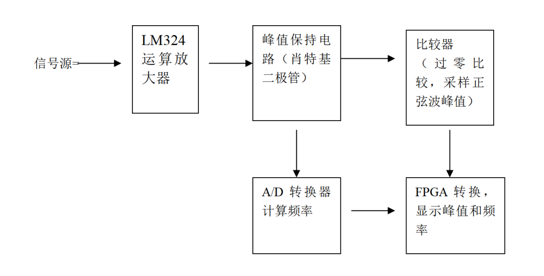
设计思想
设计一个交流信号的检测装置,对输入进行前期处理,经过 A/D 采样后数模转换,将测量结果显示出来,并具有一定的测量辅助及扩展功能。设计分别采用了 LM324 运算放大器进行信号放大,把被测输入正弦波信号最小幅度为有效值 10 毫伏,频率为 100HZ~10KHZ 的正弦信号通过两级放大,放大成接近 2 伏但不超过 2 伏的正弦信号。
然后,分为两支。一支接 LM2903 比较器以地为零点进行过零比较,输出数字信号接相应的 FPGA 用以测量频率。另一支接峰值保持电路用来保证采样到波形的最大值,再接数模转换器转换成模拟量通过门电路转换输入到相应的 FPGA 用以测量峰值,再配合用 VHDL 语言编的采用可编程逻辑器件完成数字电路的功能的程序。基本就可以较完整的实现题目要求了。
工作原理与功能
增益带宽积
运放的增益是随信号的频率变化而变化的。即输入信号的频率增大,其增益将逐渐减小,然而,其增益与其带宽的乘积是一个常数。所谓运放的带宽是指其输出电压随信号源频率的增大而使其下降到最大值的 0.707 倍时的频率范围。增益带宽积这个参数表述了某一型号运放在高增益下必然降低带宽,高带宽必然降低增益的特性。
这种情况下运放的带宽增益积也只是个理论值。由于运放输入端参数、反馈电阻、输入电阻、PCB 分布参数,运放对频率响应的变化,使运放电路在输入信号频率没有达到数据手册中标识的增益带宽积时,提前衰减到输入信号的 0.707 倍。再者,由多次谐波造成的输出电压幅度大于正常的输出电压幅度。还要考虑到压摆率对输出信号造成的失真。所以,实际应用中带宽增益积不能达到资料手册中的给出参数。这是在设计中应该注意的。所以选择运放的带宽增益积参数要高于运放实际带宽增益积的十倍比较合适。
比较器的作用
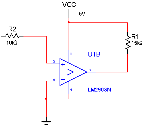
比较器是将一个模拟电压信号与一个基准电压相比较的电路。常用的幅度比较电路有电压幅度比较器,具有迟滞特性的比较器。这些比较器的阈值是固定的,有的只有一个阈值,有的具有两个阈值。我们选择如下图的电路,过零比较,把正弦信号转化成方波信号,以便 FPGA 可以通过计数器测量频率。
数模转换器
A/D 我们按照手册中的基本电路图编写,并为了测得稳定的峰值,在 A/D 的输入端我们加入了峰值保持电路(如下图),目的是能够使采样采到峰值并继续保持下去。在 A/D 输出端,我们考虑到由于 FPGA 输入端只有 3.3V,所以在 A/D 的输入端我们加入八进八出的 74HC244N,目的是使 A/D 输出的 5V 可以转换到 FPGA 的 3.3V,防止 FPGA 烧坏。
硬件电路图
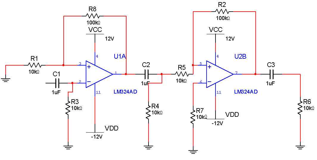
两级LM324运算放大器电路图
LM2903比较器电路图
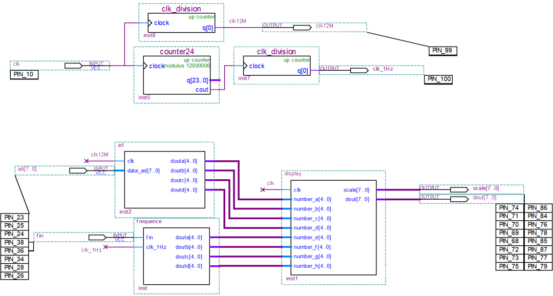
FPGA电路图
系统框图
利用ABB PLC 软件编写程序
数模转换器
library IEEE;
use IEEE.std_logic_1164.all;
use IEEE.std_logic_unsigned.all;


entity ad is
  PORT(
    clk                            : in      std_logic;
    data_ad                        : in      std_logic_vector(7 downto 0);
    douta,doutb,doutc,doutd        : out     std_logic_vector(4 downto 0)
    );
end;


ARCHITECTURE behave of ad is


  TYPE STATE_TYPE IS (s0,s1,s2,s3,s4,s5,s6,s7,s8);
  signal state: STATE_TYPE;


    signal a,b,c,d              : std_logic_vector(9 downto 0);
    signal dis_a,dis_b          : std_logic_vector(4 downto 0);
    signal dis_c,dis_d          : std_logic_vector(4 downto 0);
    signal data_transf_buff     : std_logic_vector(10 downto 0);

begin


-------------------------------------


process (clk,state)
  begin
    if clk 'event and clk ='1' then
      case state is

    when s0 = >
        data_transf_buff<="00000000000";
        a(7 downto 0)<=data_ad;
            state<=s1;
        when s1 = >
        b(7 downto 0)<=data_ad;
            state<=s2;
    when s2 = >
            c(7 downto 0)<=data_ad;
            state<=s3;
        when s3 = >
            d<= data_ad + a + b + c;

            state<=s4;
-----------------------------------------------------------------
                when s4 = >
            dis_a <= "00000"; dis_b <= "00000";
            dis_c <= "00000"; dis_d <= "00000";
            data_transf_buff(10 downto 1)<=d;
                    state<=s5;


        when s5 = >
            if data_transf_buff >= "01111101000" then
                  data_transf_buff <= data_transf_buff - "01111101000";
                  dis_a <= dis_a + 1;
                  state<=s5;
            else
                  state<=s6;
            end if;

        when s6 = >
            if data_transf_buff >= "00001100100" then
                  data_transf_buff <= data_transf_buff - "00001100100";
                  dis_b <= dis_b + 1;
                  state<=s6;
            else
                  state<=s7;
            end if;

        when s7 = >
            if data_transf_buff >= "00000001010" then
                  data_transf_buff <= data_transf_buff - "00000001010";
                  dis_c <= dis_c + 1;
                  state<=s7;
            else
                  dis_d <= data_transf_buff(4 downto 0);
                  state<=s8;
            end if;
        when s8 = >
            douta <= dis_a;  doutb <= dis_b;
            doutc <= dis_c;  doutd <= dis_d;
                    state <= s0;

       end case;
    end if;
end process;


end behave;
调频
library IEEE;
use IEEE.std_logic_1164.all;
use IEEE.std_logic_unsigned.all;


entity frequence is
  port(
       fin         : in  std_logic;
       clk_1Hz     : in  std_logic;
       douta       : out std_logic_vector(4 downto 0);
       doutb       : out std_logic_vector(4 downto 0);
       doutc       : out std_logic_vector(4 downto 0);
       doutd       : out std_logic_vector(4 downto 0)
      );
end;


architecture behav of frequence is


signal clk_half                          : std_logic;
signal r_1,r_2,r_3,r_4,r_5               : std_logic_vector(4 downto 0);
signal t_1,t_2,t_3,t_4,t_5               : std_logic_vector(4 downto 0);


begin
   process(clk_1Hz)
     begin
       if rising_edge(clk_1Hz) then
            clk_half<=NOT clk_half;
       end if;

   end process;

   process(fin,clk_half)
    begin
     if rising_edge(fin) then
         if clk_half='1' then r_1<=r_1+1;
                              if r_1 >"01001" then r_1<="00000"; r_2<=r_2+1; end if;
                              if r_2 >"01001" then r_2<="00000"; r_3<=r_3+1; end if;
                              if r_3 >"01001" then r_3<="00000"; r_4<=r_4+1; end if;
                              if r_4 >"01001" then r_4<="00000"; r_5<=r_5+1; end if;
                              if r_5 >"01001" then r_1<="01001"; r_2<="01001"; r_3<="01001";
                                                  r_4<="01001"; r_5<="01001"; end if;
         elsif clk_half='0'  then
                  r_1<="00000";r_2<="00000";r_3<="00000";r_4<="00000";r_5<="00000";
         end if;
     end if;
    end process;

  process(clk_half)
     begin
      if falling_edge(clk_half) then
          t_1<=r_1;   t_3<=r_3;  t_5<=r_5;
          t_2<=r_2;   t_4<=r_4;
      end if;
   end process;
-------------------------------------------------------------------------------------------


process(t_1,t_2,t_3,t_4,t_5)
  begin
    if t_5="00000" then


    if t_4="00000" then douta<="11111";
        else douta<=t_4; end if;


        if t_3="00000" then doutb<="11111";
        else doutb<=t_3; end if;


        if t_2="00000" then doutc<="11111";
        else doutc<=t_2; end if;

        doutd<=t_1;


    else  doutd<=t_2;doutc<=t_3;
          doutb<=t_4+"10000";
          douta<=t_5;
    end if;
end process;
end;
计数器
LIBRARY ieee;
USE ieee.std_logic_1164.all;


LIBRARY lpm;
USE lpm.all;


ENTITY counter24 IS
  PORT
  (
    clock    : IN STD_LOGIC ;
    cout    : OUT STD_LOGIC ;
    q    : OUT STD_LOGIC_VECTOR (23 DOWNTO 0)
  );
END counter24;


ARCHITECTURE SYN OF counter24 IS


  SIGNAL sub_wire0  : STD_LOGIC ;
  SIGNAL sub_wire1  : STD_LOGIC_VECTOR (23 DOWNTO 0);


  COMPONENT lpm_counter
  GENERIC (
    lpm_direction    : STRING;
    lpm_modulus    : NATURAL;
    lpm_port_updown    : STRING;
    lpm_type    : STRING;
    lpm_width    : NATURAL
  );
  PORT (
      clock  : IN STD_LOGIC ;
      cout  : OUT STD_LOGIC ;
      q  : OUT STD_LOGIC_VECTOR (23 DOWNTO 0)
  );
  END COMPONENT;


BEGIN
  cout    <= sub_wire0;
  q    <= sub_wire1(23 DOWNTO 0);


  lpm_counter_component : lpm_counter
  GENERIC MAP (
    lpm_direction = > "UP",
    lpm_modulus = > 12000000,
    lpm_port_updown = > "PORT_UNUSED",
    lpm_type = > "LPM_COUNTER",
    lpm_width = > 24
  )
  PORT MAP (
    clock = > clock,
    cout = > sub_wire0,
    q = > sub_wire1
  );
END SYN;
显示
library IEEE;
use IEEE.std_logic_1164.all;
use IEEE.std_logic_unsigned.all;


entity display is
  port(clk       : in  std_logic;
       number_a  : in  std_logic_vector(4 downto 0);
       number_b  : in  std_logic_vector(4 downto 0);
       number_c  : in  std_logic_vector(4 downto 0);
       number_d  : in  std_logic_vector(4 downto 0);
       number_e  : in  std_logic_vector(4 downto 0);
       number_f  : in  std_logic_vector(4 downto 0);
       number_g  : in  std_logic_vector(4 downto 0);
       number_h  : in  std_logic_vector(4 downto 0);
       scale     : out std_logic_vector(7 downto 0);
       dout      : out std_logic_vector(7 downto 0)
             );
end;


architecture behav of display is


signal number     :  std_logic_vector(2 downto 0);
signal LED        :  std_logic_vector(4 downto 0);
signal clk_counter:  std_logic_vector(5 downto 0);
signal clk_d      :  std_logic;


begin


process(clk)
     begin
       if rising_edge(clk) then
          clk_counter<=clk_counter+1;
          if clk_counter=0 then
                 clk_d<=not clk_d;
          end if;
       end if;
end process;

process(clk_d)
    begin
       if rising_edge(clk_d) then
            number<=number+1;
            case number(2 downto 0) is
              when "000" = > LED<=number_a; scale<="00000001";
              when "001" = > LED<=number_b; scale<="00000010";
              when "010" = > LED<=number_c; scale<="00000100";
              when "011" = > LED<=number_d; scale<="00001000";
              when "100" = > LED<=number_e; scale<="00010000";
              when "101" = > LED<=number_f; scale<="00100000";
              when "110" = > LED<=number_g; scale<="01000000";
              when "111" = > LED<=number_h; scale<="10000000";
              when others = > scale<="00000000";
            end case;
        end if;
end process;


process(LED)
    begin
       case LED(4 downto 0) is
            when "00000" = > dout <= "11000000";
            when "00001" = > dout <= "11111001";
            when "00010" = > dout <= "10100100";
            when "00011" = > dout <= "10110000";
            when "00100" = > dout <= "10011001";
            when "00101" = > dout <= "10010010";
            when "00110" = > dout <= "10000010";
            when "00111" = > dout <= "11111000";
             when "01000" = > dout <= "10000000";
           when "01001" = > dout <= "10010000";


      when "10000" = > dout <= "01000000";
            when "10001" = > dout <= "01111001";
            when "10010" = > dout <= "00100100";
            when "10011" = > dout <= "00110000";
            when "10100" = > dout <= "00011001";
            when "10101" = > dout <= "00010010";
            when "10110" = > dout <= "00000010";
            when "10111" = > dout <= "01111000";
             when "11000" = > dout <= "00000000";
           when "11001" = > dout <= "00010000";


           when "11111" = > dout <= "11111111";
           when others = > dout <= "11111111";
        end case;
end process;


end;
06
特色成果
本组在运算放大器的设计中,充分考虑到被测输入正弦波信号最小幅度为有效值 10 毫伏,而放大后输入到数模转换器的电压不能超过 2 伏而要无限接近于 2 伏。所以,在设计时,我们采用两级放大,第一级放大 10 倍,第二级根据输入信号的不同由一个小开关控制。当输入信号为 1015mv 时,采用 13 倍放大,当输入信号为 1620mv 时,采用 10 倍放大。这样,可以根据信号的峰值不同采用不同的放大级数,有利于信号的放大不是真。
-
Xilinx可编程逻辑器件的高级应用与设计技巧绝版教程2012-02-27 0
-
可编程逻辑器件2014-04-15 0
-
基于EDA技术的可编程逻辑器件在数字信号处理系统中的应用2019-06-28 0
-
可编程逻辑器件是如何发展的?2021-04-29 0
-
PLD可编程逻辑器件2021-07-22 0
-
可编程逻辑器件设计2006-03-25 986
-
可编程逻辑器件基础及应用实验指导书2010-03-24 569
-
第三十二讲 可编程逻辑器件及应用2009-03-30 1350
-
什么是PLD(可编程逻辑器件)2009-06-20 16063
-
EDA技术与应用(可编程逻辑器件)2012-05-23 852
-
可编程逻辑器件(书皮)2022-07-10 359
-
可编程逻辑器件的分类有哪些2020-06-10 27138
-
电可编程逻辑器件EPLD是如何设计的2022-08-22 987
-
可编程逻辑器件的结构2023-03-24 839
-
可编程逻辑器件测试2023-06-06 441
全部0条评论

快来发表一下你的评论吧 !
