

 基于STM32CUBEMX驱动TOF模块VL53l0x(1)----单模块距离获取的最佳实践
描述
概述
VL53L0X是新一代飞行时间(ToF)激光测距模块(不同于传统技术),采用目前市场上最小的封装,无论目标反射率如何,都能提供精确的距离测量。它可以测量2m的绝对距离,为测距性能等级设定了新的基准,为各种新应用打开了大门。
最近在弄ST的课程,需要样片的可以加群申请:615061293 。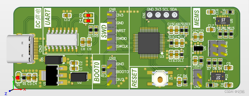
VL53L0X集成了一个领先的SPAD阵列(单光子雪崩二极管),并内嵌ST的第二代FlightSense™专利技术。
VL53L0X的940nm VCSEL发射器(垂直腔面发射激光器)完全不为人眼所见,加上内置的物理红外滤光片,使其测距距离更长,对环境光的免疫性更强,对盖片的光学串扰具有更好的稳定性。
![最近在弄ST的课程,需要样片的可以加群申请:615061293 。]
视频教学
[https://www.bilibili.com/video/BV1dH4y1D7Px/]
样品申请
[https://www.wjx.top/vm/OhcKxJk.aspx#]
源码下载
[https://download.csdn.net/download/qq_24312945/88332771](
所有功能
● 完全集成的小型化模块
○ 940 nm 激光器 VCSEL
○ VCSEL驱动器
○ 测距传感器,内嵌高级微控制器
○ 4.4 x 2.4 x 1.0 mm
● 快速,精确测距
○ 测量的绝对距离达到2m
○ 报告的距离与目标反射率无关
○ 先进的嵌入式光学串扰补偿,简化盖片的选择
● 人眼安全
○ 1类激光器件,符合最新标准IEC 60825-1:2014(第3版)要求
● 方便集成
○ 单回流焊元件
○ 无附加光学元件
○ 单电源
○ 用于器件控制和数据传输的I2C接口
○ Xshutdown(复位)和中断 GPIO
○ 可编程I2C地址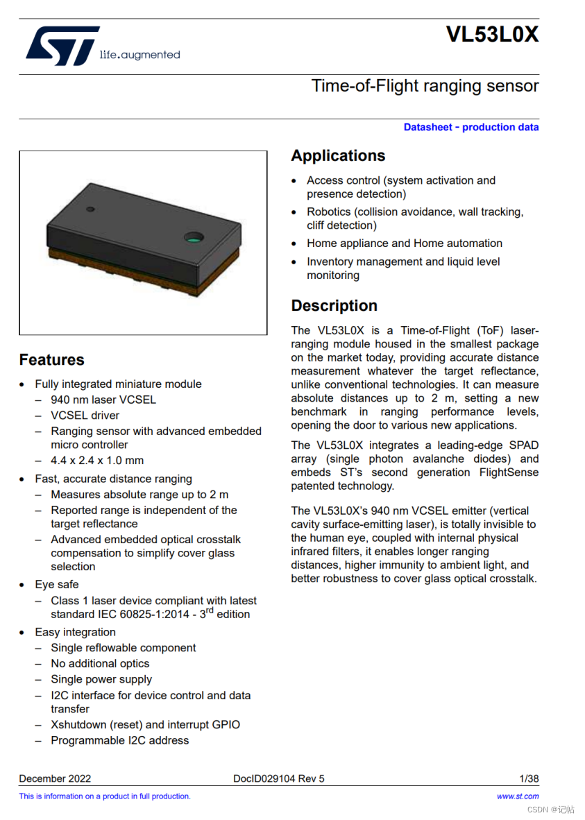
技术规范
该模块的供电要求为2.8V,适合于低电压应用场景。它通过I2C接口进行主机控制和数据通信,方便与其他设备的集成。支持最大快速模式速率,达到400k,确保高效的数据传输。
最后,VL53L0X模块具有一个默认地址为0x29的设备地址,这样在多个I2C设备共享同一总线时,可以轻松管理和区分不同的模块。
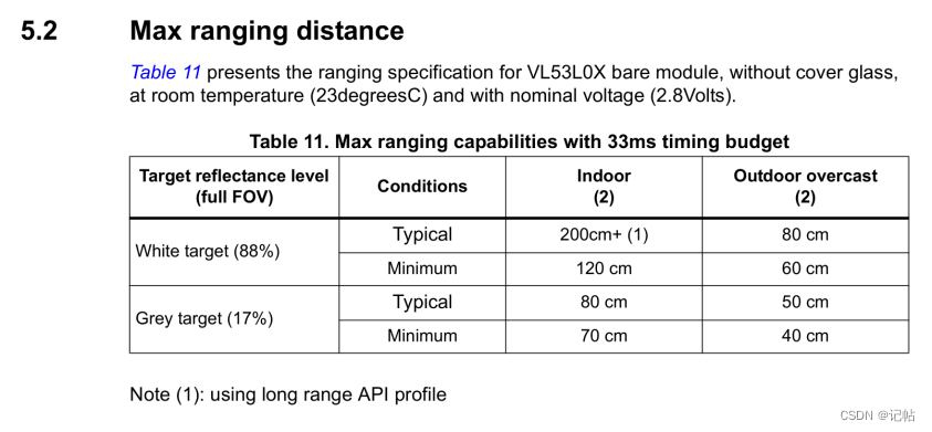
测量范围
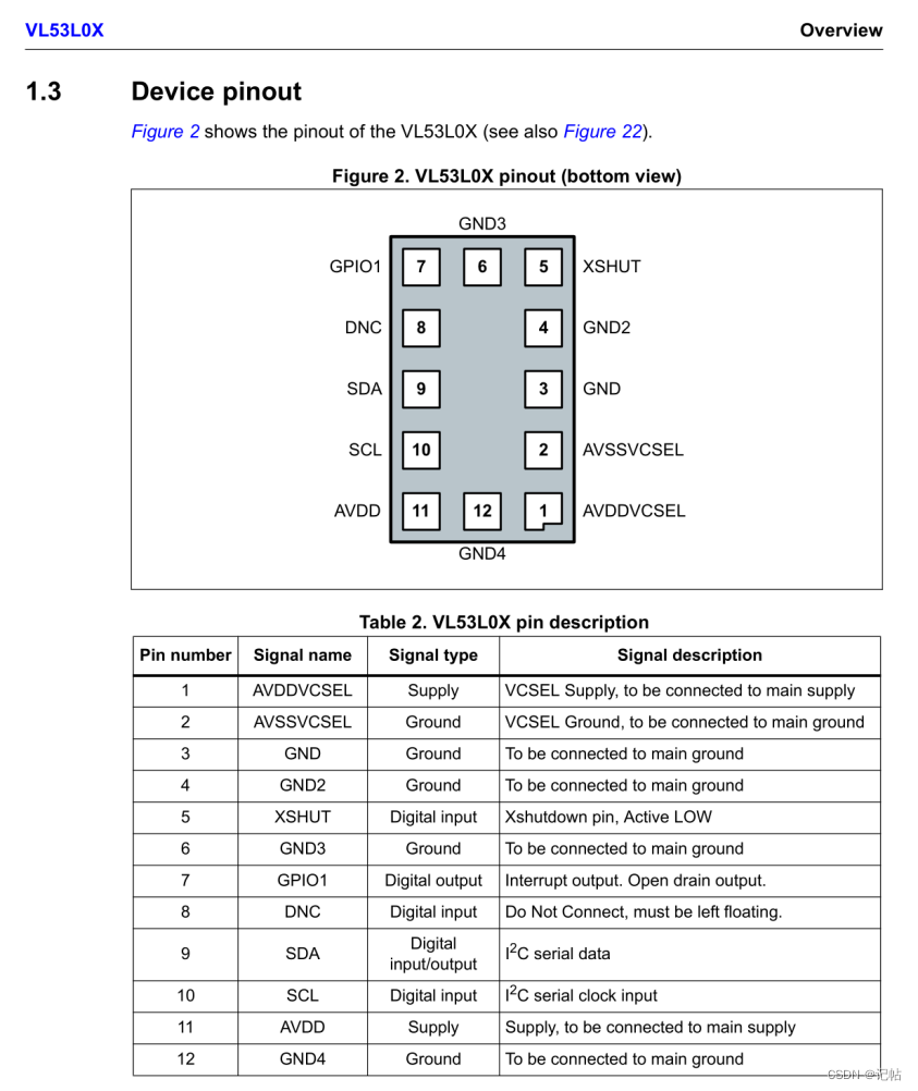
接口
VL53L0X模块接口的示意图如下所示。
接口说明
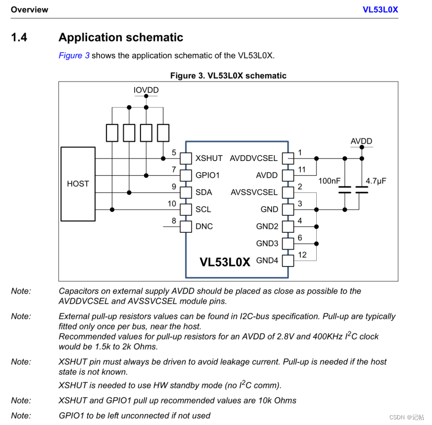
最小系统图
IIC配置
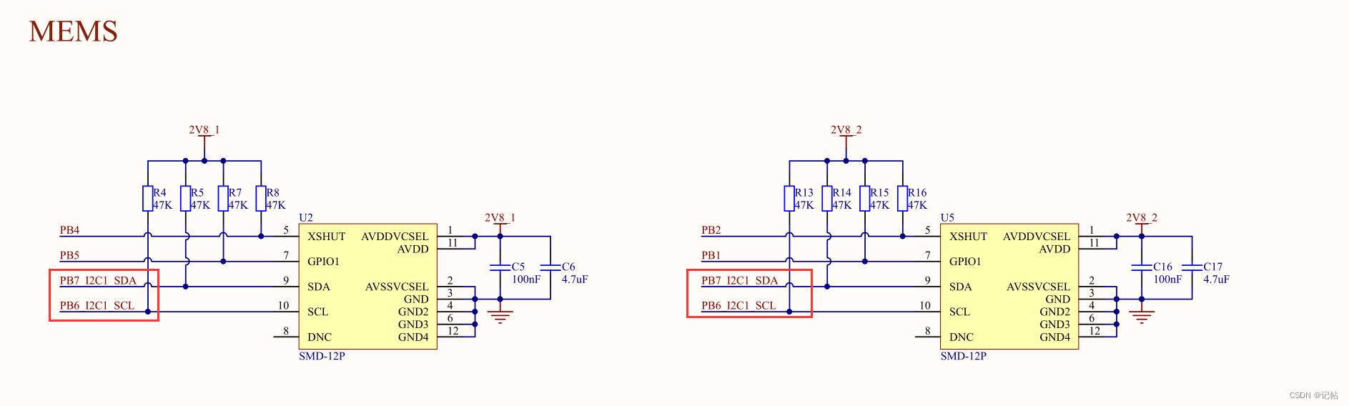
在这个应用中,VL53L0X模块通过I2C(IIC)接口与主控器通信。具体来说,VL53L0X 模块的I2C引脚连接到主控器的PB6(引脚B6)和PB7(引脚B7)两个IO口。
这种连接方式确保了模块与主控器之间的可靠数据传输和通信。PB6作为I2C总线的串行数据线(SDA),负责数据的传输和接收。而PB7则充当I2C总线的串行时钟线(SCL),用于同步数据传输的时序。
配置IIC为快速模式,速度为400k。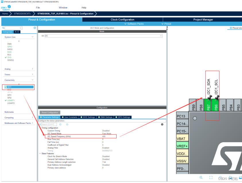
串口重定向
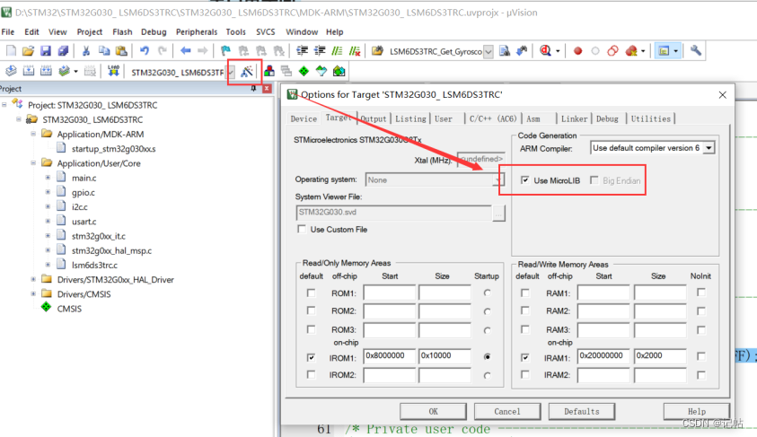
打开魔术棒,勾选MicroLIB
在main.c中,添加头文件,若不添加会出现 identifier "FILE" is undefined报错。
/* USER CODE BEGIN Includes */
#include "stdio.h"
/* USER CODE END Includes */
函数声明和串口重定向:
/* USER CODE BEGIN PFP */
int fputc(int ch, FILE *f){
	HAL_UART_Transmit(&huart1 , (uint8_t *)&ch, 1, 0xFFFF);
	return ch;
}
/* USER CODE END PFP */
模块片选
根据提供的表格信息,我们可以得知VL53L0X模块的XSHUT 引脚用作片选脚(Chip Enable),这是Xshutdown引脚,它是一个数字输入,当处于低电平状态(Active LOW)时,可以用来关闭(即"shutdown")传感器。这通常用于重置传感器或在不需要传感器测量时将其关闭以节省功耗。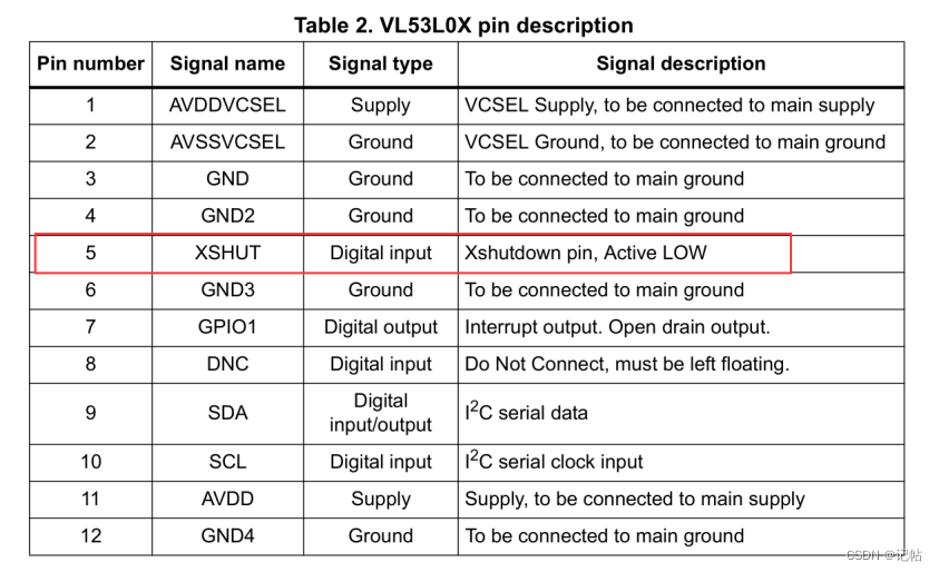
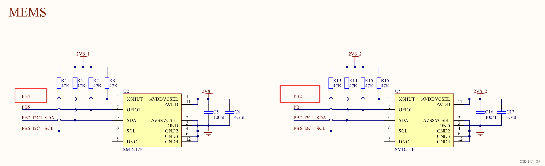
查看手册可以得知,对应的IO为PB2和PB4。
在STM32CUBEMX中配置如下所示。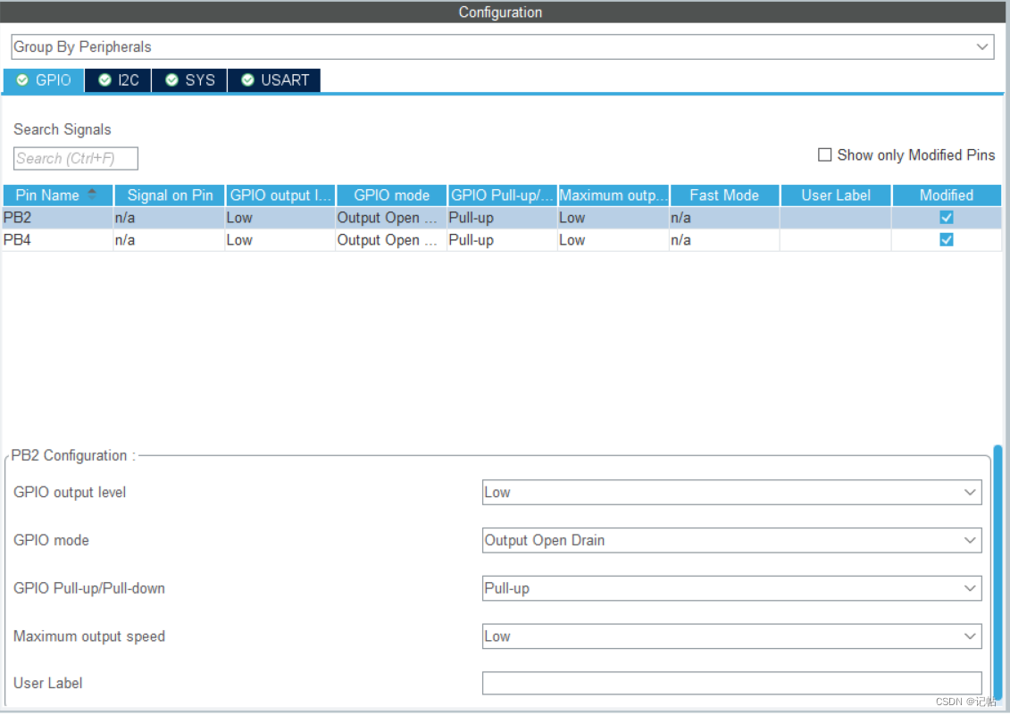
模块地址
VL53L0X模块的默认设备地址为0x29。设备地址是用来识别和通信特定设备的标识符。通过将VL53L0X模块的设备地址设置为0x29,您可以确保与该模块进行正常的通信和控制。
若添加读写位,写地址为0x52,读地址为0x53。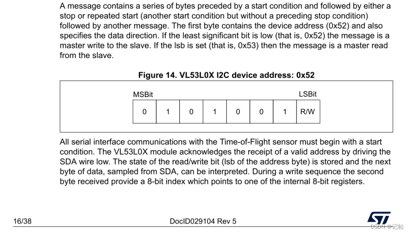
对于VL53L0X模块,默认的7位地址是0x29(二进制为010 1001),加上写位后为0x52(二进制为0101 0010),加上读位后为0x53(二进制为0101 0011)。
这意味着当主设备与VL53L0X模块进行通信时,要发送0x52地址字节进行写操作,或发送0x53地址字节进行读取操作。
extern I2C_HandleTypeDef hi2c1;

void VL53L0X_WriteByte(uint8_t add,uint8_t reg,uint8_t data)
{
	HAL_I2C_Mem_Write(&hi2c1 ,(add< < 1)|0,reg,I2C_MEMADD_SIZE_8BIT,&data,1,0xffff);

}
void VL53L0X_WriteByte_16Bit(uint8_t add,uint8_t reg,uint16_t data)
{
	uint8_t data2[2]={0,0};
	data2[0]=data > >8;
	data2[1]=data;
	HAL_I2C_Mem_Write(&hi2c1 ,(add< < 1)|0,reg,I2C_MEMADD_SIZE_8BIT,data2,2,0xffff);

}

void VL53L0X_WriteByte_32Bit(uint8_t add,uint8_t reg,uint32_t data)
{
	uint8_t data2[4]={0,0,0,0};
	data2[0]=data > >24;
	data2[1]=data > >16;
	data2[2]=data > >8;
	data2[3]=data;
	HAL_I2C_Mem_Write(&hi2c1 ,(add< < 1)|0,reg,I2C_MEMADD_SIZE_8BIT,data2,4,0xffff);

}

uint8_t VL53L0X_ReadByte(uint8_t add,uint8_t reg)
{
	uint8_t data=0;
	HAL_I2C_Mem_Read(&hi2c1 ,(add< < 1)|1,reg,I2C_MEMADD_SIZE_8BIT,&data,1,0xffff);
	return data;
}


uint16_t VL53L0X_ReadBytee_16Bit(uint8_t add,uint16_t reg)
{
	uint16_t data=0;
	uint8_t data2[2];
	HAL_I2C_Mem_Read(&hi2c1 ,(add< < 1)|1,reg,I2C_MEMADD_SIZE_8BIT,data2,2,0xffff);
	data=data2[0];
	data=data< < 8;
	data+=data2[1];

	return data;

}
参考文档
这里参考的文档问arduino的驱动代码。
https://github.com/pololu/vl53l0x-arduino/tree/master
初始化
参考程序中给出的初始化如下所示。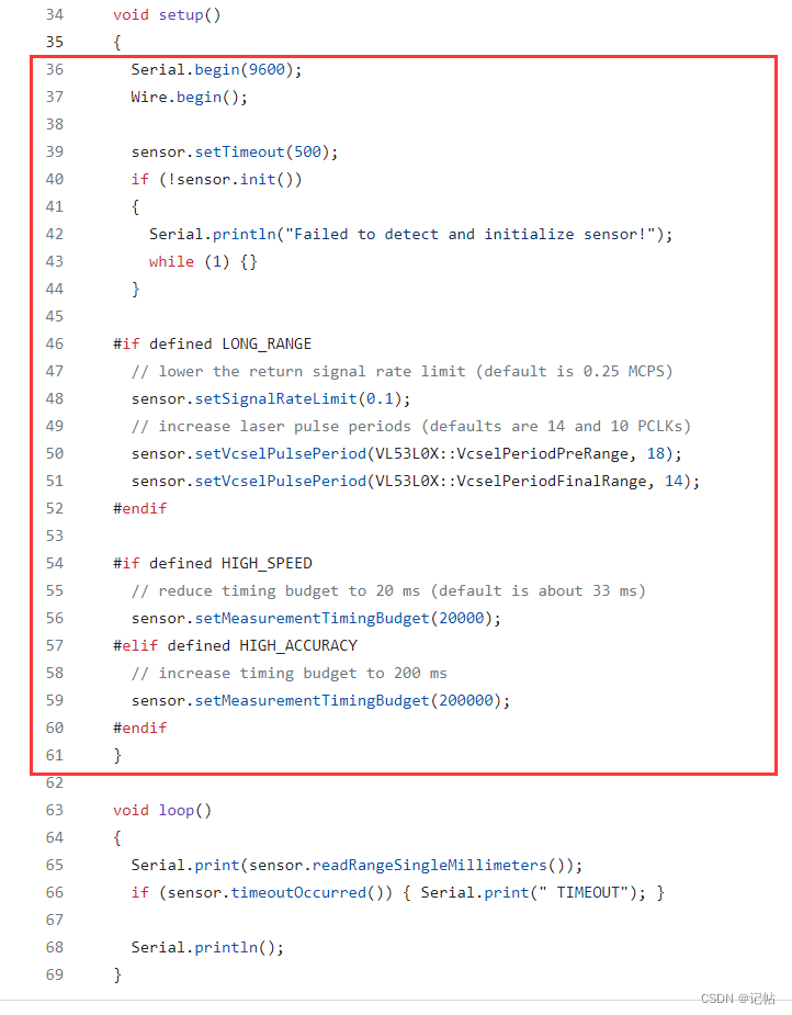
其中sensor.init()是VL53L0X的模块初始设置。
// Initialize sensor using sequence based on VL53L0X_DataInit(),
// VL53L0X_StaticInit(), and VL53L0X_PerformRefCalibration().
// This function does not perform reference SPAD calibration
// (VL53L0X_PerformRefSpadManagement()), since the API user manual says that it
// is performed by ST on the bare modules; it seems like that should work well
// enough unless a cover glass is added.
// If io_2v8 (optional) is true or not given, the sensor is configured for 2V8
// mode.
bool VL53L0X::init(bool io_2v8)
{
  // check model ID register (value specified in datasheet)
  if (readReg(IDENTIFICATION_MODEL_ID) != 0xEE) { return false; }

  // VL53L0X_DataInit() begin

  // sensor uses 1V8 mode for I/O by default; switch to 2V8 mode if necessary
  if (io_2v8)
  {
    writeReg(VHV_CONFIG_PAD_SCL_SDA__EXTSUP_HV,
      readReg(VHV_CONFIG_PAD_SCL_SDA__EXTSUP_HV) | 0x01); // set bit 0
  }

  // "Set I2C standard mode"
  writeReg(0x88, 0x00);

  writeReg(0x80, 0x01);
  writeReg(0xFF, 0x01);
  writeReg(0x00, 0x00);
  stop_variable = readReg(0x91);
  writeReg(0x00, 0x01);
  writeReg(0xFF, 0x00);
  writeReg(0x80, 0x00);

  // disable SIGNAL_RATE_MSRC (bit 1) and SIGNAL_RATE_PRE_RANGE (bit 4) limit checks
  writeReg(MSRC_CONFIG_CONTROL, readReg(MSRC_CONFIG_CONTROL) | 0x12);

  // set final range signal rate limit to 0.25 MCPS (million counts per second)
  setSignalRateLimit(0.25);

  writeReg(SYSTEM_SEQUENCE_CONFIG, 0xFF);

  // VL53L0X_DataInit() end

  // VL53L0X_StaticInit() begin

  uint8_t spad_count;
  bool spad_type_is_aperture;
  if (!getSpadInfo(&spad_count, &spad_type_is_aperture)) { return false; }

  // The SPAD map (RefGoodSpadMap) is read by VL53L0X_get_info_from_device() in
  // the API, but the same data seems to be more easily readable from
  // GLOBAL_CONFIG_SPAD_ENABLES_REF_0 through _6, so read it from there
  uint8_t ref_spad_map[6];
  readMulti(GLOBAL_CONFIG_SPAD_ENABLES_REF_0, ref_spad_map, 6);

  // -- VL53L0X_set_reference_spads() begin (assume NVM values are valid)

  writeReg(0xFF, 0x01);
  writeReg(DYNAMIC_SPAD_REF_EN_START_OFFSET, 0x00);
  writeReg(DYNAMIC_SPAD_NUM_REQUESTED_REF_SPAD, 0x2C);
  writeReg(0xFF, 0x00);
  writeReg(GLOBAL_CONFIG_REF_EN_START_SELECT, 0xB4);

  uint8_t first_spad_to_enable = spad_type_is_aperture ? 12 : 0; // 12 is the first aperture spad
  uint8_t spads_enabled = 0;

  for (uint8_t i = 0; i < 48; i++)
  {
    if (i < first_spad_to_enable || spads_enabled == spad_count)
    {
      // This bit is lower than the first one that should be enabled, or
      // (reference_spad_count) bits have already been enabled, so zero this bit
      ref_spad_map[i / 8] &= ~(1 < < (i % 8));
    }
    else if ((ref_spad_map[i / 8] > > (i % 8)) & 0x1)
    {
      spads_enabled++;
    }
  }

  writeMulti(GLOBAL_CONFIG_SPAD_ENABLES_REF_0, ref_spad_map, 6);

  // -- VL53L0X_set_reference_spads() end

  // -- VL53L0X_load_tuning_settings() begin
  // DefaultTuningSettings from vl53l0x_tuning.h

  writeReg(0xFF, 0x01);
  writeReg(0x00, 0x00);

  writeReg(0xFF, 0x00);
  writeReg(0x09, 0x00);
  writeReg(0x10, 0x00);
  writeReg(0x11, 0x00);

  writeReg(0x24, 0x01);
  writeReg(0x25, 0xFF);
  writeReg(0x75, 0x00);

  writeReg(0xFF, 0x01);
  writeReg(0x4E, 0x2C);
  writeReg(0x48, 0x00);
  writeReg(0x30, 0x20);

  writeReg(0xFF, 0x00);
  writeReg(0x30, 0x09);
  writeReg(0x54, 0x00);
  writeReg(0x31, 0x04);
  writeReg(0x32, 0x03);
  writeReg(0x40, 0x83);
  writeReg(0x46, 0x25);
  writeReg(0x60, 0x00);
  writeReg(0x27, 0x00);
  writeReg(0x50, 0x06);
  writeReg(0x51, 0x00);
  writeReg(0x52, 0x96);
  writeReg(0x56, 0x08);
  writeReg(0x57, 0x30);
  writeReg(0x61, 0x00);
  writeReg(0x62, 0x00);
  writeReg(0x64, 0x00);
  writeReg(0x65, 0x00);
  writeReg(0x66, 0xA0);

  writeReg(0xFF, 0x01);
  writeReg(0x22, 0x32);
  writeReg(0x47, 0x14);
  writeReg(0x49, 0xFF);
  writeReg(0x4A, 0x00);

  writeReg(0xFF, 0x00);
  writeReg(0x7A, 0x0A);
  writeReg(0x7B, 0x00);
  writeReg(0x78, 0x21);

  writeReg(0xFF, 0x01);
  writeReg(0x23, 0x34);
  writeReg(0x42, 0x00);
  writeReg(0x44, 0xFF);
  writeReg(0x45, 0x26);
  writeReg(0x46, 0x05);
  writeReg(0x40, 0x40);
  writeReg(0x0E, 0x06);
  writeReg(0x20, 0x1A);
  writeReg(0x43, 0x40);

  writeReg(0xFF, 0x00);
  writeReg(0x34, 0x03);
  writeReg(0x35, 0x44);

  writeReg(0xFF, 0x01);
  writeReg(0x31, 0x04);
  writeReg(0x4B, 0x09);
  writeReg(0x4C, 0x05);
  writeReg(0x4D, 0x04);

  writeReg(0xFF, 0x00);
  writeReg(0x44, 0x00);
  writeReg(0x45, 0x20);
  writeReg(0x47, 0x08);
  writeReg(0x48, 0x28);
  writeReg(0x67, 0x00);
  writeReg(0x70, 0x04);
  writeReg(0x71, 0x01);
  writeReg(0x72, 0xFE);
  writeReg(0x76, 0x00);
  writeReg(0x77, 0x00);

  writeReg(0xFF, 0x01);
  writeReg(0x0D, 0x01);

  writeReg(0xFF, 0x00);
  writeReg(0x80, 0x01);
  writeReg(0x01, 0xF8);

  writeReg(0xFF, 0x01);
  writeReg(0x8E, 0x01);
  writeReg(0x00, 0x01);
  writeReg(0xFF, 0x00);
  writeReg(0x80, 0x00);

  // -- VL53L0X_load_tuning_settings() end

  // "Set interrupt config to new sample ready"
  // -- VL53L0X_SetGpioConfig() begin

  writeReg(SYSTEM_INTERRUPT_CONFIG_GPIO, 0x04);
  writeReg(GPIO_HV_MUX_ACTIVE_HIGH, readReg(GPIO_HV_MUX_ACTIVE_HIGH) & ~0x10); // active low
  writeReg(SYSTEM_INTERRUPT_CLEAR, 0x01);

  // -- VL53L0X_SetGpioConfig() end

  measurement_timing_budget_us = getMeasurementTimingBudget();

  // "Disable MSRC and TCC by default"
  // MSRC = Minimum Signal Rate Check
  // TCC = Target CentreCheck
  // -- VL53L0X_SetSequenceStepEnable() begin

  writeReg(SYSTEM_SEQUENCE_CONFIG, 0xE8);

  // -- VL53L0X_SetSequenceStepEnable() end

  // "Recalculate timing budget"
  setMeasurementTimingBudget(measurement_timing_budget_us);

  // VL53L0X_StaticInit() end

  // VL53L0X_PerformRefCalibration() begin (VL53L0X_perform_ref_calibration())

  // -- VL53L0X_perform_vhv_calibration() begin

  writeReg(SYSTEM_SEQUENCE_CONFIG, 0x01);
  if (!performSingleRefCalibration(0x40)) { return false; }

  // -- VL53L0X_perform_vhv_calibration() end

  // -- VL53L0X_perform_phase_calibration() begin

  writeReg(SYSTEM_SEQUENCE_CONFIG, 0x02);
  if (!performSingleRefCalibration(0x00)) { return false; }

  // -- VL53L0X_perform_phase_calibration() end

  // "restore the previous Sequence Config"
  writeReg(SYSTEM_SEQUENCE_CONFIG, 0xE8);

  // VL53L0X_PerformRefCalibration() end

  return true;
}
由于一些宏定义都是注释掉了的,所以可以不去执行下面红框的指令。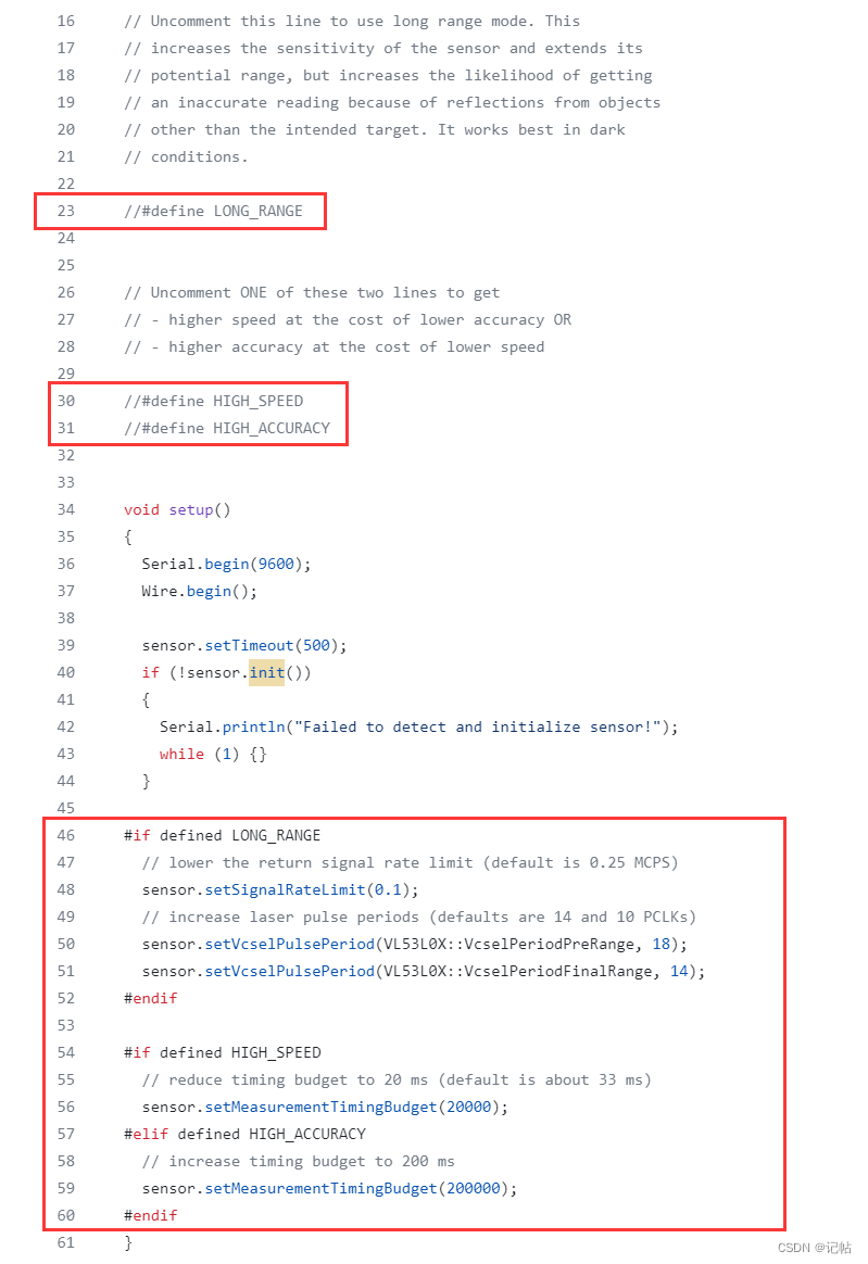
单次读取距离长度
在主程序中,主要执行的是单次获取数据。
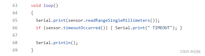
对应源码如下所示。
// Returns a range reading in millimeters when continuous mode is active
// (readRangeSingleMillimeters() also calls this function after starting a
// single-shot range measurement)
uint16_t VL53L0X::readRangeContinuousMillimeters()
{
  startTimeout();
  while ((readReg(RESULT_INTERRUPT_STATUS) & 0x07) == 0)
  {
    if (checkTimeoutExpired())
    {
      did_timeout = true;
      return 65535;
    }
  }

  // assumptions: Linearity Corrective Gain is 1000 (default);
  // fractional ranging is not enabled
  uint16_t range = readReg16Bit(RESULT_RANGE_STATUS + 10);

  writeReg(SYSTEM_INTERRUPT_CLEAR, 0x01);

  return range;
}

// Performs a single-shot range measurement and returns the reading in
// millimeters
// based on VL53L0X_PerformSingleRangingMeasurement()
uint16_t VL53L0X::readRangeSingleMillimeters()
{
  writeReg(0x80, 0x01);
  writeReg(0xFF, 0x01);
  writeReg(0x00, 0x00);
  writeReg(0x91, stop_variable);
  writeReg(0x00, 0x01);
  writeReg(0xFF, 0x00);
  writeReg(0x80, 0x00);

  writeReg(SYSRANGE_START, 0x01);

  // "Wait until start bit has been cleared"
  startTimeout();
  while (readReg(SYSRANGE_START) & 0x01)
  {
    if (checkTimeoutExpired())
    {
      did_timeout = true;
      return 65535;
    }
  }

  return readRangeContinuousMillimeters();
}
修改后如下所示。
// Returns a range reading in millimeters when continuous mode is active
// (readRangeSingleMillimeters() also calls this function after starting a
// single-shot range measurement)
uint16_t VL53L0X_readRangeContinuousMillimeters(uint8_t add)
{
  startTimeout();
uint16_t range;
  while ( (VL53L0X_ReadByte(add,RESULT_INTERRUPT_STATUS) & 0x07) == 0)
  {
    if (checkTimeoutExpired())
    {
      did_timeout = true;
      return 65535;
    }
  }
  // assumptions: Linearity Corrective Gain is 1000 (default);
  // fractional ranging is not enabled
   range= VL53L0X_ReadBytee_16Bit(add,RESULT_RANGE_STATUS + 10);

  VL53L0X_WriteByte(add,SYSTEM_INTERRUPT_CLEAR, 0x01);

  return range;
}


// Performs a single-shot range measurement and returns the reading in
// millimeters
// based on VL53L0X_PerformSingleRangingMeasurement()
uint16_t VL53L0X_readRangeSingleMillimeters(uint8_t add)
{
  VL53L0X_WriteByte(add,0x80, 0x01);
  VL53L0X_WriteByte(add,0xFF, 0x01);
  VL53L0X_WriteByte(add,0x00, 0x00);
  VL53L0X_WriteByte(add,0x91, stop_variable);
  VL53L0X_WriteByte(add,0x00, 0x01);
  VL53L0X_WriteByte(add,0xFF, 0x00);
  VL53L0X_WriteByte(add,0x80, 0x00);

  VL53L0X_WriteByte(add,SYSRANGE_START, 0x01);

  // "Wait until start bit has been cleared"
  startTimeout();
  while (VL53L0X_ReadByte(add,SYSRANGE_START) & 0x01)
  {
    if (checkTimeoutExpired())
    {
      did_timeout = true;
      return 65535;
    }
  }

  return VL53L0X_readRangeContinuousMillimeters(add);
}
测试结果
测试结果如下所示。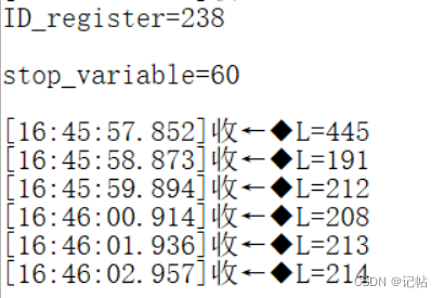
-
新一代ToF 激光测距模块VL53L0X2017-04-06 0
-
怎么使用VL53L0X和STM32L476 Nucleo64?2018-10-18 0
-
VL53L0X可以永久更改I2C地址吗?2018-10-23 0
-
如何减少VL53L0X FOV?2018-11-29 0
-
VL53L0x不会受到什么样的材料干扰2019-04-12 0
-
VL53L0x环境光灵敏度无法测量距离2019-04-15 0
-
VL53L0X配置GPIO1 INTERRUPT时的2mA电流消耗异常2019-05-10 0
-
VL53L0X X-NUCLEO-53L0A1盖玻片材料是什么2019-06-12 0
-
RT-Thread VL53L0X TOF传感器驱动设计资料实现2022-09-15 0
-
请问VL53L0X的FOV范围是多少?2022-12-08 0
-
我可以使用API VL53LX去支持VL53L1CB吗?2022-12-16 0
-
请问vl53l0x长距离模式怎么通过寄存器设置?2023-10-07 0
-
微雪电子测距传感器VL53L0X测距模块简介2020-01-06 7878
-
基于STM32CUBEMX驱动TOF模块VL53l0x(2)----修改设备地址2023-12-01 359
-
基于STM32CUBEMX驱动TOF模块VL53l0x(3)----驱动多个VL53L0X2023-12-01 529
全部0条评论

快来发表一下你的评论吧 !
