

振荡器的相位噪声仿真设置
电子说
描述
一、PSS仿真设置
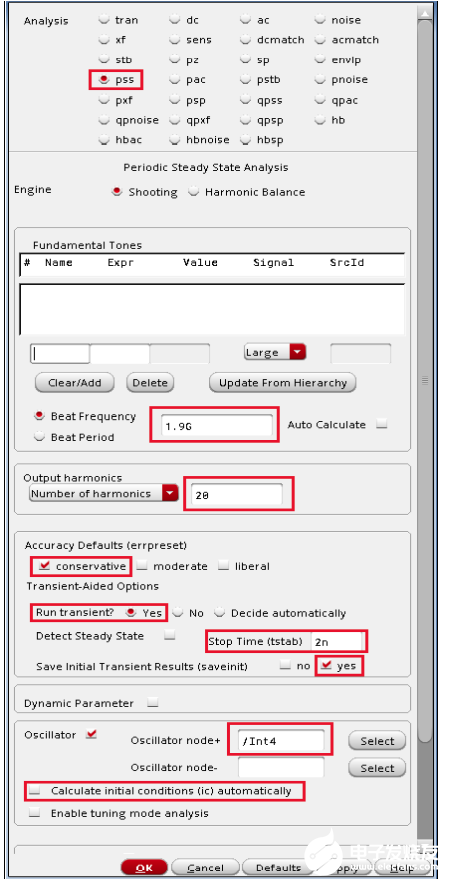
1、Beat Frequency振荡器的近似频率
2、Number of harmonics是单边谐波分析的谐波个数
3、tstab通常设置为时钟周期的2-3倍。不过tstab应该设置的足够长,保证振荡器达到稳定状态。这里2有点小,我设置为周期的20倍
4、Oscillator node,单端输出选一个即可,差分输出选两个节点。
注:如果仿真提示不收敛,可以在Simulation->Convergence Aids->initial Condition设置输出节点的初始电压,一个gnd,一个vdd
二、hb和hbnoise仿真设置
首先是hb仿真设置
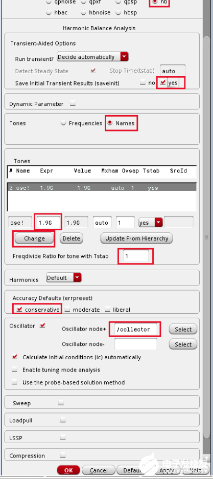
1、首先选择Oscillator Section,添加输出端口,弹出窗口直接关闭即可
2、在Tones section选择osc! 行
3、填写预估振荡频率和过采样选择1(正弦波选择1的过采样最合适)
4、Freqdivide比例设置为1表示没有分频器,即分频比为1
然后是hbnoise仿真设置
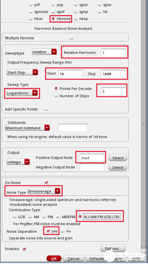
参数设置说明如下:
Type 1 in the Relative Harmonic field. You are trying to determine the noise associated with the fundamental frequency of the oscillator.
Type 10 in the Start Field in the Output Frequency Sweep Range (Hz) section.
Type 100M in the Stop Field in the Output Frequency Sweep Range (Hz) section.Set the frequency sweep range as appropriate for your circuit (or application).
Set the Sweep Type to Logarithmic.
Type 3 in the Points Per Decade field. Typically, 3 to 5 points per decade are a reasonable number to capture the noise behavior of the circuit.
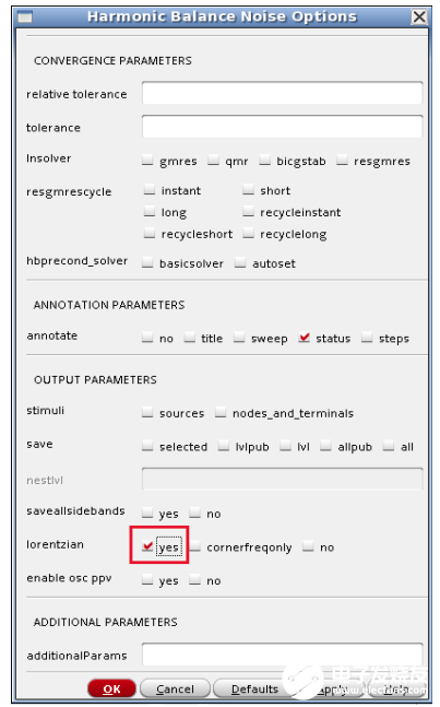
此外,为了看到低频时的相噪水平,需要在hbnoise option设置lorentzian option to yes.
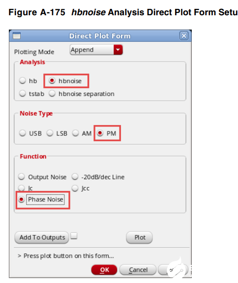
hbnoise仿真完成后
使用Direct Plot Form画出总的相位噪声曲线
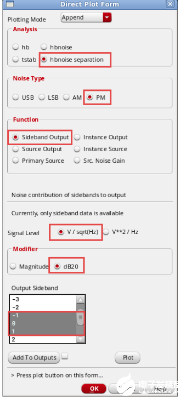
同样使用Direct Plot Form,分别画出各个-1,0和1输出边带的噪声贡献:
This will plot the noise contribution of the -1, 0, and 1 sidebands to the output. This allows the identification of which noise frequencies are causing the largest noise contribution at he output of the circuit.
找到最大噪声贡献的边带为-1边带之后,仿真-1边带各个元件的噪声大小
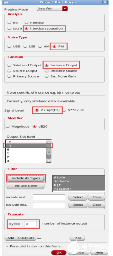
为了清楚得看到噪声源对输出得影响,
同样的设置,勾选source output查看噪声源对输出噪声贡献最大的前三名
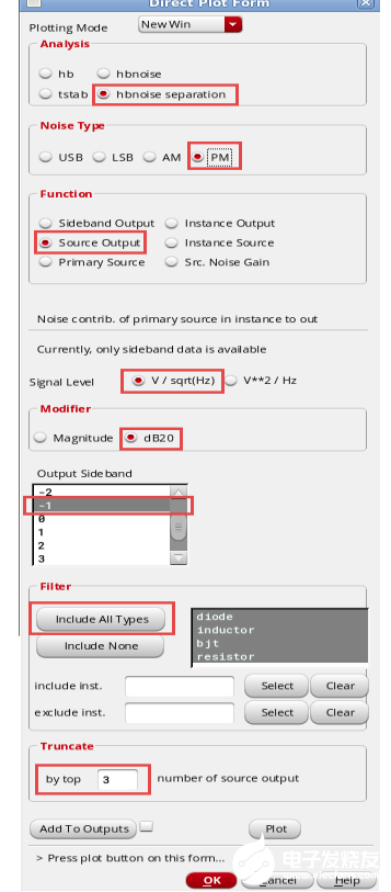
最后在Results->print可以打印在某个频偏得各个器件噪声对输出噪声的贡献比。
审核编辑:黄飞
-
DAC相位噪声性能改进包含残余相位噪声测量方法和最佳稳压器选择2019-03-19 0
-
微波振荡器PN 11729C-2的相位噪声表征2019-10-16 0
-
微波振荡器的相位噪声特性PN 11729B-12019-10-17 0
-
请问如何实现低功耗低相位噪声压控振荡器的设计?2021-04-12 0
-
分享一篇关于振荡器低频相位噪声的文章2021-06-22 0
-
20M低相位噪声晶体振荡器的设计2011-06-16 2754
-
锁相环电路中压控振荡器的分析与设计2012-01-13 1982
-
振荡器相位噪声到时间抖动的转换2017-08-03 1017
-
微波无线电用低相位噪声GaAs压控振荡器高性能SiGe锁相环对2021-04-22 453
-
将振荡器相位噪声转换为时间抖动2021-04-30 475
-
XL 系列低相位噪声石英 PLL 振荡器数据表2023-01-12 129
-
XA 系列低相位噪声石英 PLL 振荡器数据表2023-01-13 142
-
相位噪声是什么?相位噪声指标2023-12-06 1121
-
如何提高石英晶体振荡器相位噪声性能呢?2024-01-26 226
全部0条评论

快来发表一下你的评论吧 !
