

基于FreeRTOS+LVGL V8智能家居仪表盘设计
描述
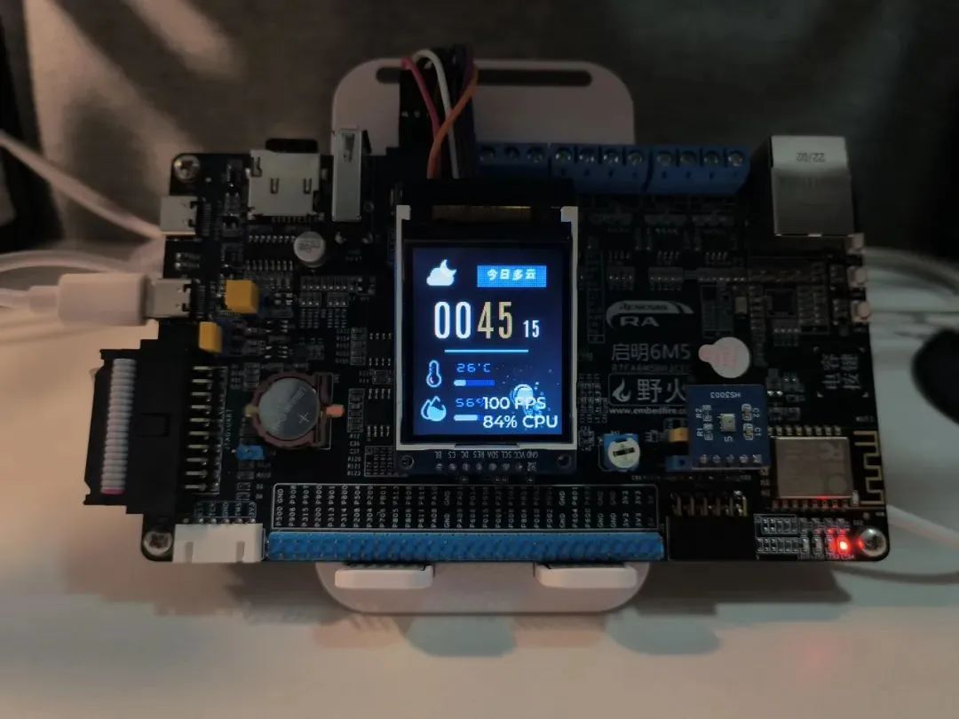
用野火启明6M5开发板制作了一个基于FreeRTOS和LVGL V8的智能家居仪表盘,颜值较高,也可以作为桌面摆件使用,具体特点如下:
采用SPI+DTC驱动1.8寸SPI屏幕,超高帧率刷屏
采用LVGL V8界面库绘制界面,有丰富控件、动画(FPS稳定50以上!)
采用ESP8266联网,使用心知天气API获取当前天气并显示到屏幕
采用ESP8266联网,通过MQTT协议连接到云服务器,上传状态数据
采用鲁班猫2安装EMQ作为MQTT服务器,接收启明6M5上传数据
采用Node-RED + Homeassistant接入家庭自动化,与智能家居设备完美联动
01
硬件平台介绍
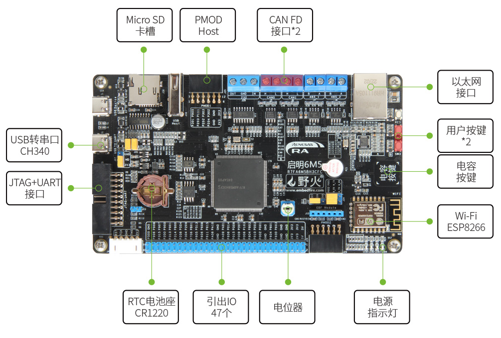
野火启明6M5开发板
使用野火启明6M5开发板来进行开发,开发板采用R7FA6M5BH3CFC作为主控芯片,有2MB Flash,2MB!!拿来开发GUI时的可发挥空间很大,接口有SD卡、以太网、PMOD、USB等等,接口很丰富,功能模块有ESP8266、电容按键和实体按键等,功能十分的丰富。
外接模块
由于开发板板载的模块已经十分丰富,这里只外接了一个SPI屏幕和温湿度传感器模块
采用1.8寸的液晶显示屏,驱动芯片为ST7735S,SPI接口。
温湿度传感器采用瑞萨的HS3003温湿度传感器,I2C接口。
外设使用情况
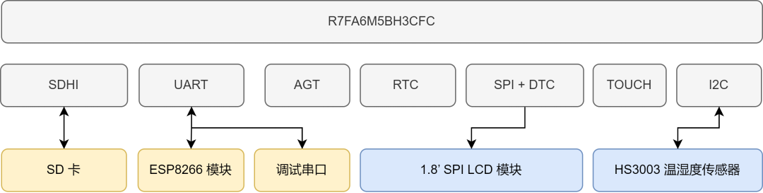
本次使用到了许多的外设,其中有如下外设
串口4 (SCI_UART4) 作为调试串口使用
串口9 (SCI_UART9) 连接到ESP8266-AT模块
SDHI连接到SD卡,提供文件系统的支持
AGT定时器为LVGL提供计时器
RTC提供实时的时间 (需要安装CR1220电池)
SPI+DTC来实现屏幕的驱动,SPI以最大速度50MHz运行
TOUCH提供电容按键
I2C (SCI_I2C6) 连接到HS3003温湿度传感器
02
软件设计方案
① 采用FreeRTOS作为本作品使用的RTOS
② 采用LVGL V8界面库来进行界面开发
③ 采用letter-shell终端组件方便开发调试
④ 采用easylogger日志组件方便调试
⑤ 采用cJSON组件配合来完成网络数据包打包与解包
多线程
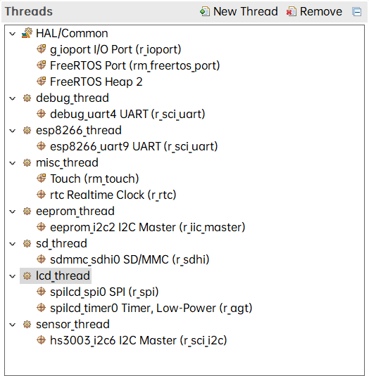
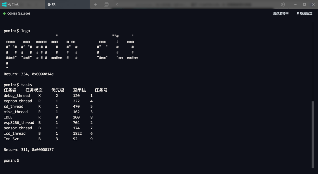
由于代码较多,所以不作全面的介绍,只介绍几个线程的任务内容和软件包的使用,文末有开源链接,作品的代码全部开源,线程列表如下图,下面依次介绍。
调试线程(debug_thread)
该线程使用了letter-shell和easylogger软件包,提供完整的终端操作支持,同时支持日志打印,例如打印esp8266线程的调试日志。
使用自定义的命令来打印当前运行的任务列表
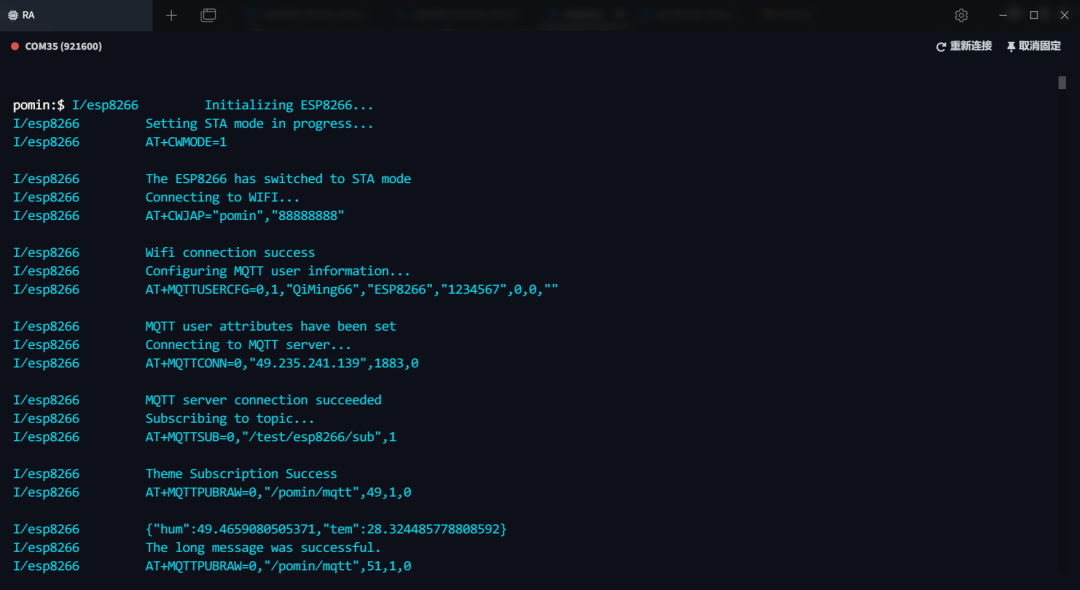
ESP8266线程(esp8266_thread)
该线程使用AT指令,实现开机自动连接Wi-Fi、自动连接MQTT服务器、订阅主题。当收到消息队列的数据后,更新温湿度数据、LED状态,然后使用cJSON来打包为JSON数据包,发布到MQTT服务器的指定主题。当收到MQTT发来的数据后,使用cJSON来解析JSON数据包,更新当前天气等。
(触摸)按键、LED、RTC线程(misc_thread)
该线程使用了MultiButton软件包,可以实现一个按键的单击、双击、连击、长按等事件的处理,这里使用触摸按键来搭配这个软件包实现触摸按键控制板载的LED亮灭,并且发送状态信息到消息队列中,交由ESP8266线程上传到服务器端。
该线程同时也使用了RTC时钟,每秒触发一次中断,发送当前时间到消息队列中,交由LCD线程来显示当前时间。
SD卡线程
该线程使用了Fatfs来挂载文件系统,自动将SD卡挂载到1: 分区下,提供给LVGL FS接口,实现LVGL加载SD卡中的文本、图片等文件。
屏幕驱动线程(lcd_thread)
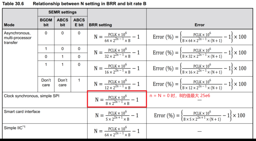
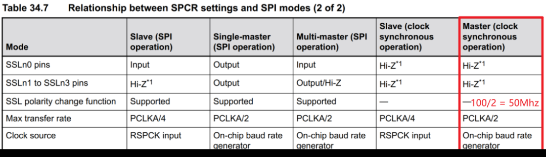
屏幕驱动使用硬件SPI+DTC的方案,这里没有使用SCI上的SPI接口,因为根据瑞萨6M5的文档得知挂在SCI上的SPI最大时钟频率为25Mhz,而直接连接的SPI最大时钟频率为50Mhz,显然使用直连SPI接口可以获得更快的刷屏速度。
该线程会接收多个线程传入的消息队列:接收RTC时钟中断发来的消息队列,在LVGL中注册的timer callback函数中读取后显示到屏幕上,每秒刷新一次时间数据;接收温湿度线程发来的消息队列,读取后更新当前屏幕上的温湿度数值和进度条控件。
温湿度传感器线程(sensor_thread)
该线程每隔十秒使用硬件I2C来读取HS3003的数据并解算出温湿度数据,发送温湿度数据到消息队列中,交由ESP8266线程来上传到服务器和LCD线程来显示到屏幕。
LVGL移植、界面设计LVGL移植
在本作品中对LVGL的显示接口和文件系统接口做了移植,下面对LVGL的显示接口移植做介绍,LVGL的显示接口只有三个函数需要修改,分别是缓冲区的初始化、屏幕的初始化和刷屏函数的接口,对于屏幕的初始化在lcd_thread中已经完成过,所以只需完成缓冲区的初始化和刷屏函数接口的适配。
为了实现更快的刷屏速度,使用官方提供的example2程序,并且给LVGL申请一个全屏缓冲区,搭配SPI+DTC的全屏缓冲区,需要更新屏幕上的数据时只需要搬运数据即可。
上下滑动查看完整内容
左右滑动即可查看完整代码
#if 1 /********************* * INCLUDES *********************/ #include "lv_port_disp.h" #include/********************* * DEFINES *********************/ #ifndef MY_DISP_HOR_RES #warning Please define or replace the macro MY_DISP_HOR_RES with the actual screen width, default value 320 is used for now. #define MY_DISP_HOR_RES 128 #endif #ifndef MY_DISP_VER_RES #warning Please define or replace the macro MY_DISP_HOR_RES with the actual screen height, default value 240 is used for now. #define MY_DISP_VER_RES 160 #endif /********************** * TYPEDEFS **********************/ /********************** * STATIC PROTOTYPES **********************/ static void disp_init(void); static void disp_flush(lv_disp_drv_t * disp_drv, const lv_area_t * area, lv_color_t * color_p); /********************** * STATIC VARIABLES **********************/ /********************** * MACROS **********************/ /********************** * GLOBAL FUNCTIONS **********************/ void lv_port_disp_init(void) { /*------------------------- * Initialize your display * -----------------------*/ disp_init(); /*----------------------------- * Create a buffer for drawing *----------------------------*/ /* Example for 2) */ static lv_disp_draw_buf_t draw_buf_dsc_2; static lv_color_t buf_2_1[MY_DISP_HOR_RES * MY_DISP_VER_RES]; lv_disp_draw_buf_init(&draw_buf_dsc_2, buf_2_1, NULL, MY_DISP_HOR_RES * MY_DISP_VER_RES); /*Initialize the display buffer*/ /*----------------------------------- * Register the display in LVGL *----------------------------------*/ static lv_disp_drv_t disp_drv; /*Descriptor of a display driver*/ lv_disp_drv_init(&disp_drv); /*Basic initialization*/ /*Set up the functions to access to your display*/ /*Set the resolution of the display*/ disp_drv.hor_res = MY_DISP_HOR_RES; disp_drv.ver_res = MY_DISP_VER_RES; /*Used to copy the buffer's content to the display*/ disp_drv.flush_cb = disp_flush; /*Set a display buffer*/ disp_drv.draw_buf = &draw_buf_dsc_2; /*Required for Example 3)*/ //disp_drv.full_refresh = 1; /* Fill a memory array with a color if you have GPU. * Note that, in lv_conf.h you can enable GPUs that has built-in support in LVGL. * But if you have a different GPU you can use with this callback.*/ //disp_drv.gpu_fill_cb = gpu_fill; /*Finally register the driver*/ lv_disp_drv_register(&disp_drv); } /********************** * STATIC FUNCTIONS **********************/ /*Initialize your display and the required peripherals.*/ static void disp_init(void) { /*You code here*/ } volatile bool disp_flush_enabled = true; /* Enable updating the screen (the flushing process) when disp_flush() is called by LVGL */ void disp_enable_update(void) { disp_flush_enabled = true; } /* Disable updating the screen (the flushing process) when disp_flush() is called by LVGL */ void disp_disable_update(void) { disp_flush_enabled = false; } /*Flush the content of the internal buffer the specific area on the display *You can use DMA or any hardware acceleration to do this operation in the background but *'lv_disp_flush_ready()' has to be called when finished.*/ extern uint8_t lcd_buff[160][128][2]; static void disp_flush(lv_disp_drv_t * disp_drv, const lv_area_t * area, lv_color_t * color_p) { if(disp_flush_enabled) { /*The most simple case (but also the slowest) to put all pixels to the screen one-by-one*/ int32_t x; int32_t y; for(y = area->y1; y <= area->y2; y++) { for(x = area->x1; x <= area->x2; x++) { /*Put a pixel to the display. For example:*/ /*put_px(x, y, *color_p)*/ lcd_buff[y][x][0] = color_p->full >> 8; lcd_buff[y][x][1] = color_p->full; color_p++; } } } /*IMPORTANT!!! *Inform the graphics library that you are ready with the flushing*/ lv_disp_flush_ready(disp_drv); } #else /*Enable this file at the top*/ /*This dummy typedef exists purely to silence -Wpedantic.*/ typedef int keep_pedantic_happy; #endif
对于刷屏函数的移植只需实现数据的搬运,代码如下:
extern uint8_t lcd_buff[160][128][2];
static void disp_flush(lv_disp_drv_t * disp_drv, const lv_area_t * area, lv_color_t * color_p)
{
    if(disp_flush_enabled) {
        /*The most simple case (but also the slowest) to put all pixels to the screen one-by-one*/


        int32_t x;
        int32_t y;
        for(y = area->y1; y <= area->y2; y++) {
            for(x = area->x1; x <= area->x2; x++) {
                /*Put a pixel to the display. For example:*/
                /*put_px(x, y, *color_p)*/
                lcd_buff[y][x][0] = color_p->full >> 8;
                lcd_buff[y][x][1] = color_p->full;
                color_p++;
            }
        }
    }


    /*IMPORTANT!!!
     *Inform the graphics library that you are ready with the flushing*/
    lv_disp_flush_ready(disp_drv);
}
在lcd_thread线程的while循环中只需使用SPI发送全屏缓冲到屏幕,代码如下:
void lcd_push_buff(void) {
    R_SPI_Write(spilcd_spi0.p_ctrl, lcd_buff, LCD_W * LCD_H * 2, SPI_BIT_WIDTH_8_BITS);
}
/* 下面是主函数调用 */
void lcd_thread_entry(void* pvParameters) {
    FSP_PARAMETER_NOT_USED(pvParameters);
    lcd_setup();


    while (1) {
        lcd_push_buff();
        lv_task_handler();
    }
}
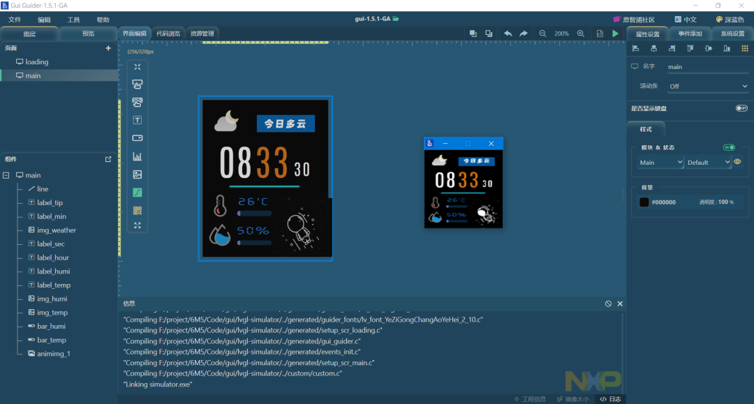
界面设计与仿真
采用NXP的GUI Guider作为PC端的设计器和仿真器,GUI Guider可以在PC端完成一站式的LVGL界面设计与仿真,例如下图所示:
在GUI Guider中对两个页面分别创建了一个定时器,并且实现了两个回调函数,代码如下,通过这个定时器回调函数来实现周期性的刷新屏幕显示的内容,更新网络连接状态、当前温湿度、当前时间、当前天气等数据。
左右滑动即可查看完整代码
void timer_main_reflash_cb(lv_timer_t *t)
{
    static uint32_t tick;
    lv_ui * gui = t->user_data;
#ifdef __ARMCC_VERSION
    float sensor_info[2];
    if (pdTRUE == xQueueReceive(g_sensor2lcd_queue, sensor_info, pdMS_TO_TICKS(0))) {
        lv_bar_set_value(gui->main_bar_humi, (uint32_t) sensor_info[0], LV_ANIM_ON);
        lv_bar_set_value(gui->main_bar_temp, (uint32_t) sensor_info[1], LV_ANIM_ON);
        lv_label_set_text_fmt(gui->main_label_humi, "%2d%%", (uint32_t) sensor_info[0]);
        lv_label_set_text_fmt(gui->main_label_temp, "%2d'C", (uint32_t) sensor_info[1]);
    }
    rtc_time_t get_time;
    if (pdTRUE == xQueueReceive(g_clock2lcd_queue, &get_time, pdMS_TO_TICKS(0))) {
        lv_label_set_text_fmt(gui->main_label_hour, "%02d", get_time.tm_hour);
        lv_label_set_text_fmt(gui->main_label_min, "%02d", get_time.tm_min);
        lv_label_set_text_fmt(gui->main_label_sec, "%02d", get_time.tm_sec);
    }
    uint32_t num = 0;
    if (pdTRUE == xQueueReceive(g_esp2lcd_queue, &num, pdMS_TO_TICKS(0))) {
        if (num > 38) {
            num = 99;
        }
        char path [30];
        sprintf(path, "1lvgl/weather/%d.jpg", num);
        lv_img_set_src(gui->main_img_weather, path);
    }
#endif
}


const char str_ch[][40] = {
    "连接WI-Fi...",
    "连接WI-Fi失败!",
    "连接WI-Fi成功!",
    "连接MQTT服务器...",
    "连接MQTT服务器失败",
    "订阅MQTT主题...",
};


void timer_loading_reflash_cb(lv_timer_t *t)
{
    static uint32_t num = 0;
    lv_ui * gui = t->user_data;
#ifdef __ARMCC_VERSION
    if (pdTRUE == xQueueReceive(g_esp2lcd_queue, &num, pdMS_TO_TICKS(0))) {
        lv_label_set_text(gui->loading_tip, str_ch[num]);
        lv_bar_set_value(gui->loading_process, num * 20, LV_ANIM_ON);
        if (num >= 5) {
            setup_scr_main(gui);
            lv_scr_load(gui->main);
        }
    }
#else
    num += 3;
    lv_label_set_text(gui->loading_tip, str_ch[num / 20]);
    lv_bar_set_value(gui->loading_process, num, LV_ANIM_ON);
    if (num >= 100) {
        setup_scr_main(gui);
        lv_scr_load(gui->main);
    }
#endif
}
MQTT与服务器解析
使用ESP8266模块连接到MQTT服务器,因为MQTT也是自建的EMQX服务器,自由度相对onenet平台要大很多,这里的上传数据、下载数据都是统一由MQTT服务器搭配node-red来完成,避免来回地将ESP8266切换为透传模式来实现HTTP访问,全由服务器来进行数据的处理与打包,拖拽化开发自定义的MQTT消息处理流程不香吗?
例如上传当前温湿度、LED状态、知心天气API获得当前的天气数据的流程设置如下:
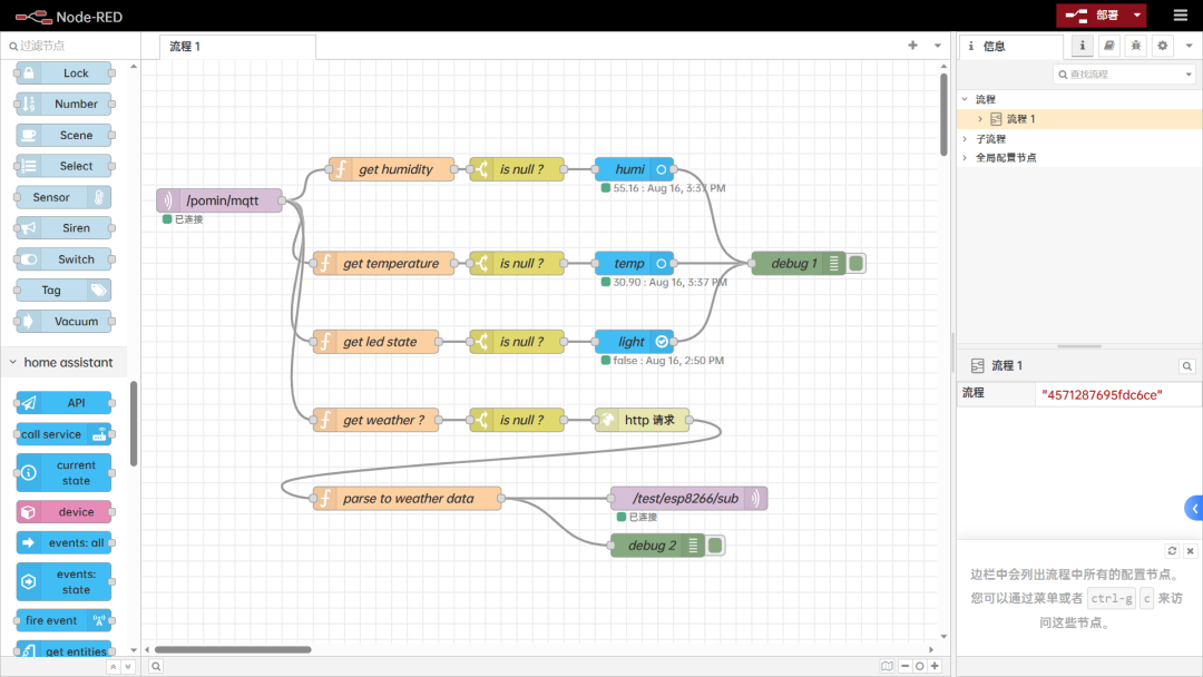
服务器端解析温湿度数据时,上传的数据包格式为 JSON 数据,形如
{“hum”:51.498504638671872,”tem”:30.258193969726564}
为了解析MQTT的数据包,需要编写一段代码来实现数据类型的限定,这里还加了保留到两位小数,其中的 “get humidity” 等函数只需编写如下一段JavaScript代码,经过解析后得到湿度数据,传入后面的 “is null ?” 节点后若不为空就更新数据给Homeassistant的设备。
var field = msg.payload.hum;
var out;


if (field == null) {
    out = { payload: null };
} else {
    if (typeof field === 'number') {
        if (Number(field) === Math.round(field)) {
            /* 整数 */
            out = { payload: field };
        } else {
            /* 小数 */
            out = { payload: field.toFixed(2) };
        }
    } else if (typeof field === 'boolean') {
        /* 布尔 */
        out = { payload: field };
    } else if (typeof field === 'string') {
        /* 字符串 */
        out = { payload: field };
    }
}
return out;
经过HTTP访问知心天气的API后,耶对得到的JSON结果进行解析,消息形如:
{
    "results": [
        {
            "location": {
                "id": "WTW3SJ5ZBJUY",
                "name": "Shanghai",
                "country": "CN",
                "path": "Shanghai,Shanghai,China",
                "timezone": "Asia/Shanghai",
                "timezone_offset": "+08:00"
            },
            "now": {
                "text": "Cloudy",
                "code": "4",
                "temperature": "35"
            },
            "last_update": "2023-08-13T1214+08:00"
        }
    ]
}
解析代码也非常简单,text为当前的天气文本,code为当前的天气代码:
var text = msg.payload.results[0].now.text;
var code = msg.payload.results[0].now.code;


return { payload: code };
然后发送最终的天气码到主题 /test/esp8266/sub,这个主题是ESP8266已经订阅的,ESP8266线程完成数据的获取,然后发送天气码到消息队列,LCD读取消息队列,得到天气码,然后读取SD卡中的天气图标,显示到屏幕上,完成天气图标的更新。
03
最终效果
联网进度显示界面
开机自动联网、进度条提示,FPS最低50!这个瑞萨的MCU跑LVGL完全无压力
实时温湿度、时间数据显示
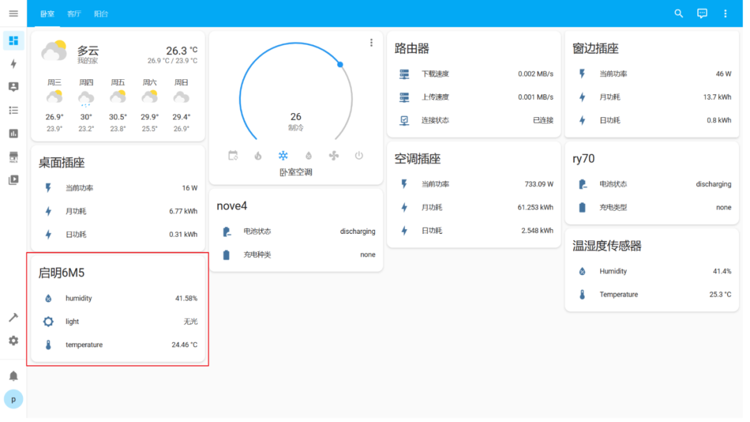
接入Homeassistant记录温湿度数据
通过node-red接入到HA作为一个设备显示当前的温湿度数据和板载LED的状态
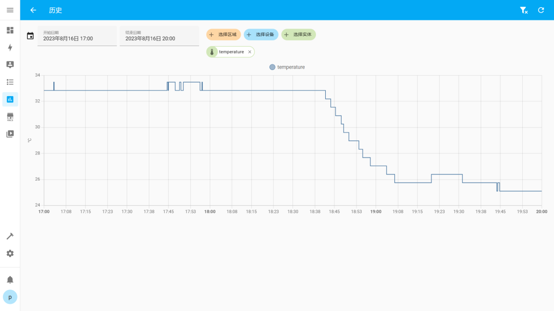
温度数据的历史曲线(开了空调温度是直线下降啊)
湿度数据的历史曲线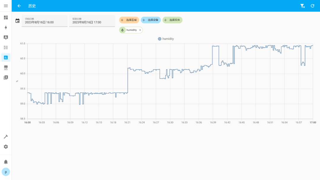
天猫精灵获取板载LED状态
设置了单击触摸按键开关LED2亮灭的逻辑操作,然后会自动上传这个LED2的开关状态到MQTT服务器上,通过node-red来上传到Homeassistent,搭配巴法云平台接入到语音助手,我用的是天猫精灵,可以通过语音助手获取到当前LED2的状态,当然只是做一个演示,可以实现的自动化智能家居当然还有很多的玩法。
04
视频展示
05
总结
本作品开发过程中体会到了瑞萨的开发软件十分的易用,方便,也学习到了LVGL V8、MQTT服务器数据包的收发,node-red桥接MQTT消息包到HA的知识。
完成以上所有的功能后Flash使用了1MB出头(主要是GUI的资源文件),这个单片机是有2MB的Flash,界面开发还有很大的发挥空间。
1.8寸的小屏比较小,可以换成更大的屏和增加触摸,但是RA6M5没有专门的屏幕驱动外设,如果要拓展成并口MCU屏或者RGB屏还是有点受限的。
使用到了如下第三方软件包,除FatFs使用BSD外别的均为MIT开源协议
CJSON
EasyLogger
FatFs
letter-shell
MultiButton
LVGL V8
FreeRTOS
审核编辑:刘清
-
原装IC网基于瑞萨单片机的仪表盘(总线型)解决方案2013-02-26 0
-
汽车仪表盘解决方案2014-01-07 0
-
虚拟仪表盘是未来的趋势吗?2014-09-25 0
-
OBD车速和仪表盘车速的对应?2015-03-03 0
-
基于labview汽车仪表盘的设计2015-06-01 0
-
汽车仪表盘MCU背后的故事2019-07-09 0
-
一文浅析汽车仪表盘2021-08-31 0
-
开发汽车obd数字仪表盘的过程记录2021-12-20 0
-
仪表盘指示灯不亮电机不转及仪表盘指示灯亮电机不转的原因及处理2009-11-11 2844
-
Visteon高科技仪表盘近图赏析2010-03-11 1557
-
汽车仪表盘中图形显示技术应用2011-03-26 2061
-
电子图形仪表盘解决方案-瑞萨-彭总2016-12-26 750
-
用于仪表盘的电源解决方案2018-08-20 3503
-
克服汽车仪表盘电源设计难题2022-11-03 361
全部0条评论

快来发表一下你的评论吧 !
