

数据链路层发送与接收的处理过程及涉及到的模块
FPGA/ASIC技术
描述
1 数据链路层
数据链路层包括发送和接收两个部分,本章主要介绍数据流从进入到发射器的数据链路层到从接收器的数据链路层出来的所经过的具体处理过程以及涉及到的模块。
下面的图21和图22分别是发送数据链路层和接收数据链路层的内部结构图,本章节将从发送链路层开始介绍每一个具体模块的功能,同时由于接收链路层中包含的模块总是发送的模块的功能是相对的,所以在介绍发送链路层中的模块时,将同时介绍接收部分模块的功能。
进入链路层的数据是在传输层映射为数据帧的,进入数据链路层的数据以帧为最小单元,而数据链路层工作在charcter clock时钟域,所以在进入数据链路层后,farme data 将先经过Frame_to_octet模块,Frame_to_octet模块将输入的数据帧转换成octet的数据流。
数据流在Scrambler模块将进行加扰处,加扰的功能是可选择的。
经过加扰处理的数据流经过alignment_character_generator模块将进行字节替换,字节替换的目的是为了检测数据通道数据流是否工作正常。
Mux模块通过TX_controller模块选择需要数据的数据流
数据流在8b/10bcoder模块中将进行编码操作,并最终输出到serdes_tx模块。
TX_contrller 为数据链路层的控制模块,该模块通过control interface与上层接口交互控制信息,并对控制信息进行解析,进而控制数据链路层的工作流程。
Initial_lane_alignment_sequcence_generator是不同数据通道间的同步序列的生成模块,该模块将在系统启动同步后,产生所需要的同步序列。
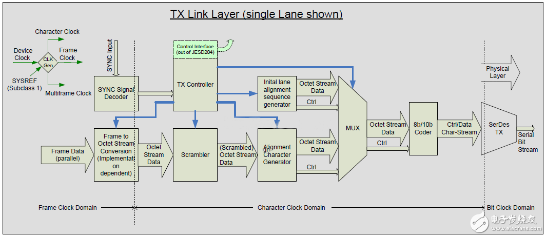
图21:数据链路层发送器的内部结构图
在接收器部分,数据链路层的数据流的具体操作如下:
物理层的serdes模块将输入的1bit的串行数据流转换为10bit并行数据流,并通过特殊的对齐字节完成数据流的对齐,并将对齐完后的数据通过8b/10b进行解码,并出输出8bit位宽的octet数据流。
解码输出的数据流将通过lane_alignment_buffering_detection_monitoring模块,该模块将通过对校准字符在数据帧中的位置,来判断现阶段的数据传输不同通道间是否同步。
接下来数据流经过Frame_alignment_detection_monitoring模块,该模块也是通过对校准字符在数据帧中的检测来数据帧是否发生对齐的错误。
在经过两级的对齐检测后,数据将进入descrambler模块进行数据的解扰。
解扰后的数据流将通过octet_to_frame模块从新组合成数据帧,传输到数据传输层。
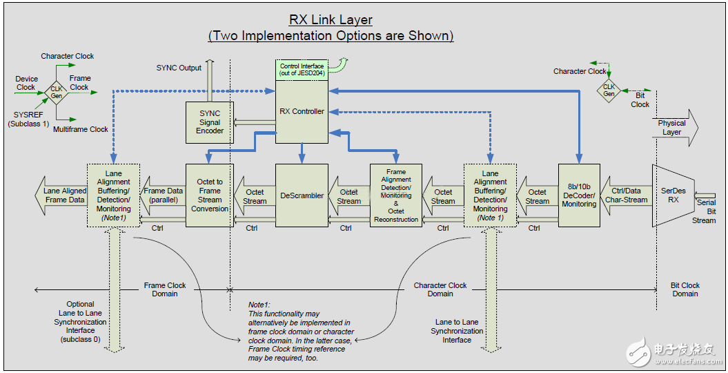
图22:数据链路层接收射器的内部结构图
以上便是系统中数据链路层对数据流的控制和处理流程,SystemC的模型中,上述的每一个模块将有相对应的模型,并且SystemC中模块的名字将与上述图中的模块名称保持一致。
1.1 RX Controller
Rxcontroller作为数据链路成的控制核心,其内部需要完成的工作主要为两个方面,一方面通过数据接口与上层进行控制数据交换,一方面完成数据链路层的工作状态控制,本章将系统的介绍数据链路层的工作状态控制。
在Rx controller内需要完成的工作包括:code group synchronization、initial frame synchronization,这两部分表现为两个状态机的控制,完成数据流的同步和数据帧的同步。
1.1.1 code group synchronization
code group synchronization的功能在系统上电或者要求系统从新同步时完成数据流的同步,该同步的具体的过程是在serdes的CDR模块中实现的,完成1bit数据流到10bit的串行转换。具体的同步细节如下:
在同步要求开始后,接收控制器发送同步请求,此时SYNC信号将保持低电平,发射器在接收到同步请求后,将会发送comma码:/K/=/K28.5/
接收控制器在接收以下的情况下降释放同步请求:
Subclass 0 devcies:在接收到4个有效的K码后,在任何数据帧的边界释放同步请求。
Subclass 1和Subclass 2:在接收到4个有效的k码后,在数据的复帧(mutliframe)的边界释放同步请求,也就是将SYNC信号拉高。
在接收到另外4个有效的comma码后,系统将认为数据code group synchronization完成。
当接收到一个无效的数据时,状态机将进入检测模式。
如果在检测模式中,累积收到3个无效数据时,认为系统未同步。
在检测模式中,如果检测到4个正确数据后会认为系统同步正常。
同步请求由接收器通过SYNC信号传输到发送器,并且SYNC低电平有效,SYNC信号只有在frame clock 的上升沿才会发送变化,但是也分两种情况:
Subclass 0:任何frame clock的上升沿
Subclass 1和Subclass 2:任何frame clock 和multiframe clock对齐的上升沿。
SYNC信号的低电平持续时间必须大于5个数据帧或者9个octet的持续时间。
Code groupsynchronization 同步的状态机转换图如图23所示,变量的具体意义在表1中有详细的描述。
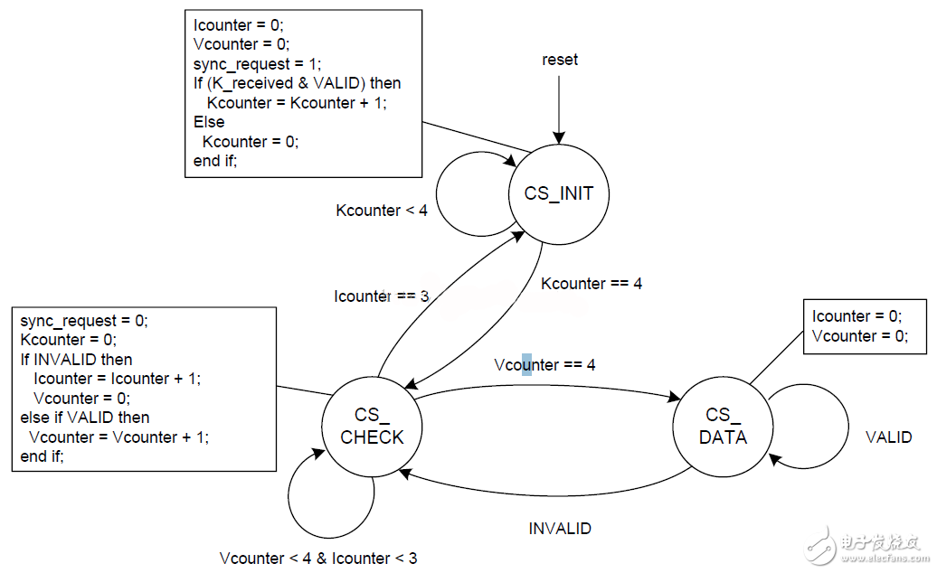
图23:Code groupsynchronization state machine
Variable
Meaning
Icounter
Counter used in the CS_CHECK phase to count the number of invalid symbols
INVALID
Asserted by receiver to indicate that the current symbol is an invalid symbol given the current running disparity.
K_received
Asserted when the current symbol corresponds to control character K28.5
Kcounter
Counter used in the CS_INIT phase to count the number of valid K28.5 symbols
sync_request
Asserted by receiver when loss of code group synchronization has been detected. Note that sync_request does not drive SYNC~ directly, as SYNC~ assertion/de-assertion is based on more than just the sync_request signal described here.
VALID
Asserted by receiver to indicate that the current symbol is a valid symbol given the current running disparity.
Vcounter
Counter used in the CS_CHECK phase to count the number of successive valid symbols
code groupsynchronization只需要在SYNC有效时进行,而在数据的正常传输时,两个相邻字节中的某1bit出现错误,也将有可能出现comma码,而此时的comma码将不能用来作为同步的检测的标准。
1.1.2 Initial frame synchronization
Initial framesynchronization 的状态机如图24所示,该系统复位时,状态机将进入initial state,octet counter 将会被清零,而的code group synchronization 将在系统复位后生成同步请求,在这种情况下,framesynchronization 将一直处于initialstate。

图23:frame synchronizationstate machine
Frame synchronization的状态机将在code group synchronization完成后,并且发送器停止发送K码后进入FS_DATA状态,在该状态下,octet counter将会进行计算,以标记当前的octet在frame中的位置,octet counter的计数范围是:0 到F-1.如果有同步请求状态机将直接回到FS_INIT状态,但是如果有各个接受器的情况下,其他接受器发送SYNC请求时,当前接收器并不知道有同步请求的情况下,状态机只能通过检测连续的K28.5来判断状态机是否跳转。
如果K28.5被检测到,状态机将进入FS_CHECK状态,在FS_CHECK状态中,octet counter将继续计数,如果有4个K28.5被检测到,状态机将直接跳转到initial 状态。
Variable
Meaning
any_sync_request
A sync request asserted by any receiver connected to the link.
CHECK_ALIGNMENT
Perform frame alignment monitoring, see subclause 7.3
F
Number of octets per frame
Kcounter
Counter used in the FS_CHECK phase to count the number of K28.5 symbols
K_received
Asserted when the current symbol corresponds to control character K28.5 (valid or invalid)
Ocounter
Counter used to mark the position of the current octet in the frame.
sync_request
Asserted by receiver when loss of code group synchronization has been detected or if another error requires re-initialization.
1.2 Tx controller
Tx controller主要功能与Rx controller是保持一致的,其内部需要完成状态如下图所示:
具体的流程如下:
在系统复位后,状态机进入SYNC状态,在该状态下发送器将持续的发送K28.5的comma码,在SYNC信号被释放后的第一个数据帧到来时,状态机将跳转到INIT_LANE状态。
在LINIT_LANE状态下,状态机将通过控制信号控制Initial lanealignment sequence generator模块开始生产lane同步的序列,并控制MUX模块输出Initial lane alignment sequence。
在Initial lane alignment sequence发送完毕后,状态机将进入正常的数据发送状况,并在系统要求同步时进入SYNC状态。
Variable
Meaning
7C_octet
Asserted when the scrambler outputs a 0x7C (28.3) octet
alignment_sent
Used to indicate a /K28.3/ or /K28.7/ has been sent in the previous frame.
FC_octet
Asserted when the scrambler outputs a 0xFC (28.7) octet
frame_end
Asserted by transmitter to indicate end of frame.
(multi)frame_start
Asserted by transmitter to indicate start of frame for devices belonging to the NMCDA-SL device class, or start of multiframe for devices belonging to other device classes. (See clause 9).
lane_seq_end
Asserted by transmitter to indicate end of initial lane alignment sequence
multiframe_end
Asserted by transmitter to indicate end of multiframe. Only to be asserted if both sides of the lane support lane synchronization.
NewOvalue
Value of last octet in current frame
OldOvalue
Used for storage of last octet in frame
SEND_A
Send /K28.3/ symbol
SEND_DATA
Send code group belonging to current data octet
SEND_F
Send /K28.7/ symbol
SEND_K
Send /K28.5/ symbol
SEND_LANE_SEQ
Send initial lane alignment sequence
sync_request_tx
asserted when transmitter detects a synchronization request
1.3 Initial frame synchronization
在系统数据链路建立起来时,数据帧的同步将通过以下方式实现:
在code group synchronization期间,发送器将一直发送标志符comma码K28.5。
在code group synchronization结束后,在接收器接收到第一个不是K28.5的字符开始,认为是数据帧的开始,如果发送器发送的是initial lanealignment sequence,那么K28.5后面紧跟的将是K28.0。
在第一个K28.0以后,接收器认为每F个octet为一个数据帧。
1.3.1 Frame alignment monitoring andcorrection
1.3.1.1 Alignment charaters
数据帧的对齐通过对齐标志符comma码来完成,这些comma将在特定的情况下插入到数据流中,接收器将在确定接收到的comma有效时,将以comma在数据帧的位置为标志,从新的同步接收器中的数据帧,在一般的情况下,系统认为多次在数据帧的某一个位置检测到comma,才会认为该comma是有效的,并且以此作为依据来从新同步接收器中的数据帧。
对齐数据帧的标准符是comma码/F/=/K28.5/,但是如果发送和接收器都支持通道间的通道,那么comma码/A/=/28.3/也将会出现在复帧的结束,他也可以作为数据帧同步的标志符。
根据数据是否进行加扰处理,对于对齐标志符的处理将分为两种情况。
1.3.1.2 Character replacement withoutscrambling
在接收器和发送器都支持通道同步的情况下,对齐标志符的在发送器内的替换和在接收器中的还原需要遵循如下的操作:
当前数字帧的最后一个octet,当前复帧的最后一个octe除外,等于上一次数据帧的最后一个octet,那么当前数据帧的最后的octet将用/F/=/K28.7/来代替,但是如果上数据帧已经发生了对齐标志符,本次数据帧将不进行替换。
当前数据帧的最后一个octet,并且是复帧的最后一个octet,等于上一次数据帧的最后一个octet,那么当前数据帧的最后的octet将用/A/=/K28.3/来代替,即使上一次数据帧已经发生了对齐标志符,本次数据帧也会进行替代
在接收器中,在接收到对齐标志符/F/或者/A/时,接收器需要用上一数据帧中位置相同的数据进行替代。
如果接收和发送器中,有某一个器件不支持通道同步,对齐标志符的替换将遵循如下的原则:
当前数字帧的最后一个octet,当前复帧的最后一个octe除外,等于上一次数据帧的最后一个octet,那么当前数据帧的最后的octet将用/F/=/K28.7/来代替,但是如果上数据帧已经发生了对齐标志符,本次数据帧将不进行替换。
在接收器中,在接收到对齐标志符/F/时,接收器需要用上一数据帧中位置相同的数据进行替代。
1.3.1.3 Character replacement withscrambling
在接收器和发送器都支持通道同步的情况下,对齐标志符的在发送器内的替换和在接收器中的还原需要遵循如下的操作:
当前数字帧的最后一个octet,当前复帧的最后一个octe除外,等于0xFC时,那么当前数据帧的最后的octet将用/F/=/K28.7/来代替。
当前数据帧的最后一个octet,并且是复帧的最后一个octet,等于0x7C时,那么当前数据帧的最后的octet将用/F/=/K28.3/来代替。
在接收器中,在接收到对齐标志符/F/或者/A/时,接收器需要用0xFC或者0x7C替代。
如果接收和发送器中,有某一个器件不支持通道同步,对齐标志符的替换将遵循如下的原则:
当前数字帧的最后一个octet,当前复帧的最后一个octe除外,等于0xFC时,那么当前数据帧的最后的octet将用/F/=/K28.7/来代替。
在接收器中,在接收到对齐标志符/F/时,接收器需要用0xFC替代。
1.3.1.4 Frame alignment character generator
对齐标志符的检测与校准的处理过程如图24所示,具体的变量信息解释如表4所示,当数据流中没有提供足够的机会产生数据对齐标志符时,数据帧的对齐的校准的功能可以通过控制接口屏蔽。
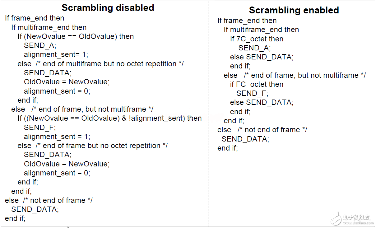
图24:Frame alignmentcharacter generator
Variable
Meaning
7C_octet
Asserted when the scrambler outputs a 0x7C (28.3) octet
alignment_sent
Used to indicate a /K28.3/ or /K28.7/ has been sent in the previous frame.
FC_octet
Asserted when the scrambler outputs a 0xFC (28.7) octet
frame_end
Asserted by transmitter to indicate end of frame.
(multi)frame_start
Asserted by transmitter to indicate start of frame for devices belonging to the NMCDA-SL device class, or start of multiframe for devices belonging to other device classes. (See clause 9).
lane_seq_end
Asserted by transmitter to indicate end of initial lane alignment sequence
multiframe_end
Asserted by transmitter to indicate end of multiframe. Only to be asserted if both sides of the lane support lane synchronization.
NewOvalue
Value of last octet in current frame
OldOvalue
Used for storage of last octet in frame
SEND_A
Send /K28.3/ symbol
SEND_DATA
Send code group belonging to current data octet
SEND_F
Send /K28.7/ symbol
SEND_K
Send /K28.5/ symbol
SEND_LANE_SEQ
Send initial lane alignment sequence
sync_request_tx
asserted when transmitter detects a synchronization request
1.3.1.5 Frame alignment monitoring andcorrection
对齐标志符的检测与校准的处理过程如图25所示,具体的变量信息解释如表5所示,当数据流中没有提供足够的机会产生数据对齐标志符时,数据帧的对齐的校准的功能可以通过控制接口屏蔽。
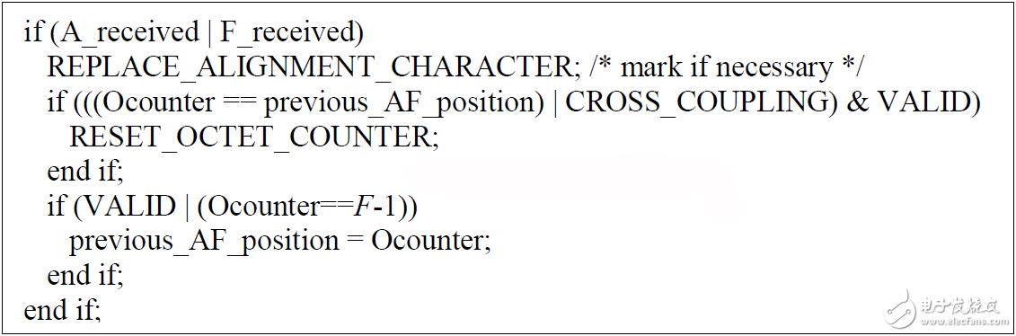
图25:Frame alignmentmonitoring and correction
Variable
Meaning
A_received
Asserted when the current symbol, before possible substitution in lane alignment monitoring, corresponds to control character K28.3 Note: detection of K28.3 is not required in NMCDA-SL DACs.
CROSS_COUPLING
Frame misalignment expected because of cross coupling between lane and frame alignment
F
Number of octets per frame
F_received
Asserted when the current symbol corresponds to control character K28.7
Ocounter
Counter used to mark the position of the current octet in the frame. Octet indexing starts from 0.
previous_AF_position
Variable into which to store the position in the frame of a K28.3 or K28.7 symbol
REPLACE_ALIGNMENT_CHARACTER
Replace the alignment character at the decoder output by:
? The data character decoded or used at the same position in the previous frame when scrambling is disabled
? The data character with the same value when scrambling is enabled
?
Mark the possition of a K28.3 character if needed in subsequent lane synchronization or lane alignment monitoring.
RESET_OCTET_COUNTER
Reset octet counter to zero at reception of next octet
VALID
Asserted by receiver to indicate that the current symbol is a valid symbol given the current running disparity.
1.4 Initial lane synchronization
在正常数据的发送与接收前,需要对系统进行通道间的同步,以保证不同通道数据在接收输出是同步的,在一个合适的时间点上,所以的发送器将同时发送字节对齐标志位/A/=/28.3,但是由于不同通道间的延时不同,会导致接收器接收到标志字符的时间是不同的。所以当接收器接收到标志字符/A/时,每一个接收器都将从A以后的序列存储起来,并通过ready标准位通知其他通道,该通道已经接收到有效的对齐字符,当系统中的所有通道都已经接收到有效的对齐字符时,系统将在一个同一时间点将缓存的数据进行释放,这样便保证了系统中所有通道数据的同步输出。
支持JESD204B的器件是可以让发送与接收之间保持固定延迟的,对于系统中的某一个接收器件没有接收到有效的对齐字符而其他器件正常接收时,JESD204B定义了具体的出错处理机制。
不同通道间的同步是通过通道同步序列(initial lane alignment sequence)来完成的,通道同步的序列将在code group synchronization完成后立即发送,initial lane alignment sequence是不经过加扰的,对于ADC器件来说initiallane alignment sequence的长度固定为4个multiframe,对于DAC器件来说,在Subclass 1和Subclass 2中,initial lane alignment sequence的要求长度也是4个multiframe,所以,对于FPGA来说,initial lane alignment sequence的长度必须可以编程,长度范围是4-256,其中multiframe的长度是K个frame,K的取值范围为:1-32,而multiframe中octet的个数范围为:17-1024。
对于JESD204B的发送器来说,K的值必须是可编程的,而JESD204B的接收器中,K的值是建议可编程,JESD204的接收器必须明确定义对于K值的处理是是要求还是建议,而在本次的建模中,K值都是可编程的。
initial lanealignment sequence的结构如图26所示,每复帧开始标志位为/R/=/28.0/,结束标准位为/A/=/28.3/,R标志着initial lane alignment sequence的开始,A标志着initiallane alignment sequence每一复帧的结束。标志位A表示每一复帧的结束并不仅仅用于initial lane alignment sequence,在正常的数据发送中也会用到,在initial lane alignment sequence的第二个复帧中,包含了系统配置的参数,从复帧的第三个字节开始,K28.4作为第二个标志字符,标志着配置字节的开始。
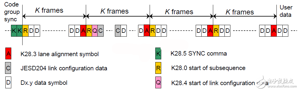
图26:initial lane alignmentsequence的结构
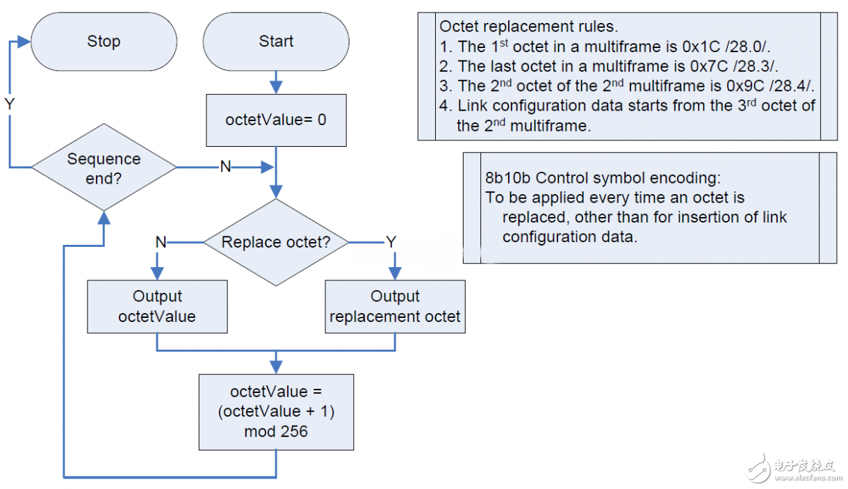
图27:initiallane alignment sequence生成的流程图内容
initial lane alignment sequence的生成流程图如上图所示,数据复帧的第一个字节为0x1c/28.0/,结束字节为/28.3/,在第二复帧的第二个字节为0x9c/28.4/,配置字符是从第二复帧的第3字节开始。
1.4.2 Link configuration data andencoding
下表为系统中配置参数的具体解释和参考图。
Parameter
Description
Parameter Range
Field
Encoding
ADJCNT
Number of adjustment resolution steps to adjust DAC LMFC.
Applies to Subclass 2 operation only.
0 … 15
ADJCNT<3:0>
Binary value
ADJDIR
Direction to adjust DAC LMFC 0 – Advance 1 – Delay
Applies to Subclass 2 operation only
0 … 1
ADJDIR<0>
Binary value
BID
Bank ID – Extension to DID
0 ... 15
BID<3:0>
Binary value
CF
No. of control words per frame clock period per link
0 ... 32
CF<4:0>
Binary value*
CS
No. of control bits per sample
0 ... 3
CS<1:0>
Binary value
DID
Device (= link) identification no.
0 ... 255
DID<7:0>
Binary value
F
No. of octets per frame
1 ... 256
F<7:0>
Binary value minus 1
HD
High Density format
0 ... 1
HD<0>
Binary value
JESDV
JESD204 version 000 – JESD204A 001 – JESD204B
0 … 7
JESDV<2:0>
Binary Value
K
No. of frames per multiframe
1 ... 32
K<4:0>
Binary value minus 1
L
No. of lanes per converter device (link)
1 ... 32
L<4:0>
Binary value minus 1
LID
Lane identification no. (within link)
0 ... 31
LID<4:0>
Binary value
M
No. of converters per device
1 ... 256
M<7:0>
Binary value minus 1
N
Converter resolution
1 ... 32
N<4:0>
Binary value minus 1
N’
Total no. of bits per sample
1 ... 32
N'<4:0>
Binary value minus 1
PHADJ
Phase adjustment request to DAC Subclass 2 only.
0 … 1
PHADJ<0>
Binary value
S
No. of samples per converter per frame cycle
1 ... 32
S<4:0>
Binary value minus 1
SCR
Scrambling enabled
0 ... 1
SCR<0>
Binary value
SUBCLASSV
Device Subclass Version 000 – Subclass 0 001 – Subclass 1 010 – Subclass 2
0 … 7
SUBCLASSV
<2:0>
Binary Value
RES1
Reserved field 1
0 ... 255
RES1<7:0>
Binary value
RES2
Reserved field 2
0 ... 255
RES2<7:0>
Binary value
CHKSUM
Checksum Σ(all above fields)mod 256
0 ... 255
FCHK<7:0>
Binary value
*?CF==L?shall always be encoded as 31: control words on all lanes.?CF==31 can only occur when?L==31, see 5.1.3.
Configuration octet no.
Bits
MSB
6
5
4
3
2
1
LSB
0
DID<7:0>
1
ADJCNT<3:0>
BID<3:0>
2
X
ADJDIR<0>
PHADJ<0>
LID<4:0>
3
SCR<0>
X
X
L<4:0>
4
F<7:0>
5
X
X
X
K<4:0>
6
M<7:0>
7
CS<1:0>
X
N<4:0>
8
SUBCLASSV<2:0>
N’<4:0>
9
JESDV<2:0>
S<4:0>
10
HD<0>
X
X
CF<4:0>
11
RES1<7:0> - Set to all X
12
RES2<7:0> - Set to all X
13
FCHK<7:0>
1.4.3 Lane alignment buffering /detection and monitoring
在开始数据帧和通道对齐后,通道将会进入对齐字节检测状态,通道的对齐是通过对齐标志符/A/=/28.3/来决定的,该对齐标志符在复帧的结尾,对于对齐标识符A的插入,可以参考frame alignmentmonitoring。
在一般的情况下,不是所有的通道都会发生同时发生对齐标识符A,但是通道可以通过A在复帧中的位置来检测数据通道的数据是否同步上。
在多个接收通道的情况下,每一个接收器都应该可以从更高层的应用中授权数据链路层对链路中的数据进行从新的动态调整,已完成不同数据通道间的对齐。
数据通道中发现未对齐
发现新的对齐字符,但是不在数据复帧的帧尾
根据对齐字符缓存区中的数据进行从新对齐
如果连续接在同一个位置上接收到两个有效的A,并且不在数据复帧的结束,并且在两个A之间没有接收到有效或者无效A标识符,通道需要从新的将通道中的数据进行对齐。
如果在最近的数据帧出现通道间不对齐的可能性很大时,接收器需要将第一个接收到A的位置作为对齐的标准。
1.4.4 Lane alignment detection andmonitoring
通道间的数据检测和对齐处理过程如图27所示,图中变量的具体意思参照表8,具体的操作流程如下:
Variable
Meaning
A_received
Asserted when the current symbol, before possible substitution in frame alignment monitoring, corresponds to control character K28.3
CROSS_COUPLING
Lane misalignment expected because of cross coupling between frame and lane alignment
Fcounter
Counter used to mark the position of the current frame in the multiframe. Frame indexing starts from 0.
K
Number of frames in multiframe.
previous_A_position
Variable into which to store the position in the multiframe of a K28.3 symbol
REPLACE_A
Replace the K28.3 at the decoder output by:
? The data character decoded or used at the same position in the previous frame when scrambling is disabled
? D28.3 when scrambling is enabled
?
However, if the position of the K28.3 is required in subsequent frame alignment monitoring, the K28.3 shall not be replaced or it shall be marked.
RESET_FRAME_COUNTER
Reset frame counter to zero at reception of next frame
INITIATE_SYNC_CHECK
In receivers belonging to a MCDA device class (see clause 9), if authorized via the control interface, initiate a synchronization check between the LMFCs via one of the methods supported by the device class and subclass.
VALID
Asserted by receiver to indicate that the current symbol is a valid symbol given the current running disparity.
1.5 Scrambler and Descrambler
加扰编码和解扰编码存在JESD204 TX和RX的模块中,并可以通过控制字使能是否对数据流进行加扰。
加扰模块都是针对单独的数据通道,不会出现不同数据通道的数据混合加扰的情况,也就是说每一个数据通道有自己独立的加扰通道。
加扰编码模块的功能是为了增加数据流中的高频分量,减小数据流中连续0和1的个数。如果出现长时间的连续“1”或连续“0”,会影响接收端从数字信号中提取时钟。
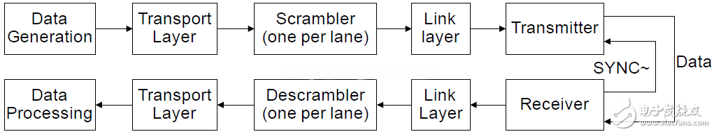
图28: Functional location of scrambler and descrambler
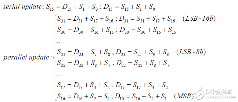
1.5.1 加扰公式
1+x[14]+x[15]
该公式的作用周期可以长达32767bit,非常适合对频谱敏感的收发应用,而解扰器只需要2个字节缓存就能解扰。
1.5.2 加扰的流程
加扰器解扰器都是通过数据流串行输入实现的,最小的处理单位为帧,加扰与解扰的顺序是由高位到低位。具体的流程如下图所示:
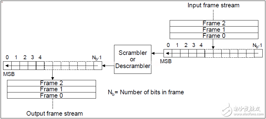
图29:Serial scrambling
1.5.3 加扰的方式
加扰的实现方式可以分为两种,串行加扰和并行加扰,串行加扰的时钟域为发送接口的串行时钟速率,虽然串行的加扰方式实现简单,但是工作的频率很高,RTL的实现难度要大于并行加扰模式,因此设计中采用并行加扰模式。
串行加扰和并行加扰的流程图如下图所示:
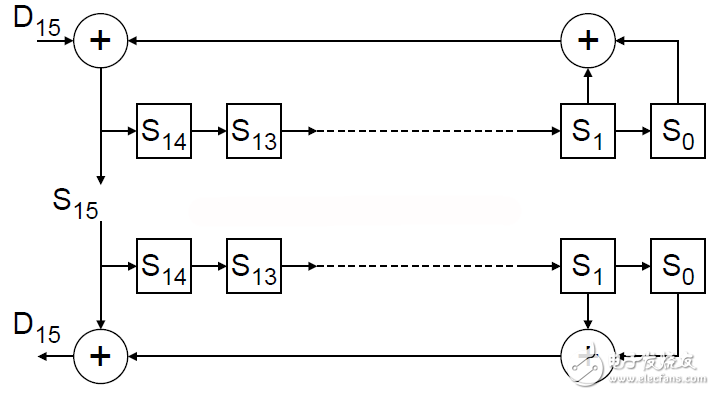
图30:Serial scrambler anddescrambler implementation
scrambler模块加入了使能信号,其结构如下图所示,当en信号无效时,scrambler模块将会被bypass,同时在code group synchronization sequence和transmission of an initial lane alignment sequence发送时,scrambler也是bypass的。在使能scrambler后,scrambler和descramber模块将会有两个octet的数据延迟。
1.6 8b/10 Encoder andDecoder/monitoring
8b/10b编码的原理是将一组连续的8位数据分解成两组数据,一组3位,一组5位,经过编码后分别成为一组4位的代码和一组6位的代码,从而组成一组10位的数据发送出去。相反,解码是将一组10位的输入数据经过变换得到8位数据位。数据值可以统一的表示为DX.Y或KX.Y,其中D表示为数据代码,K表示为特殊的命令代码。X表示输入的原始数据的低5位EDCBA,Y表示输入的原始数据的高3位HGF。因此8b/10b编码逻辑可分解为两个子逻辑块,一个5b/6b编码器(EDCBA<—>iedcba)和一个3b/4b编码器(HGF<—>jhgf)。编码原理图如下图所示。
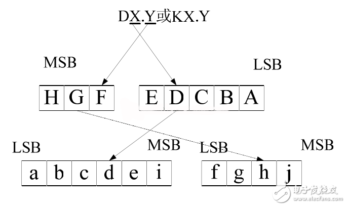
图30:8b/10 Encoder and Decoder
在8b/10b编码过程中,会出现字符不一致的情况,即一组字符中“1”和“0”的个数不一致的情况,这种情况称作差异度。当字符中的“0”比“1”多时,称作负极性;“1”比“0”多时,称作正极性;“0”和“1”相等时,为零极性。编码规则规定,非零极性的编码结果(包括4位结果,6位结果和组合的10位结果)的极性必须依次翻转[1]。比如,如果6位编码结果具有正的极性,则接下来的4位结果应该具有负的极性,如果接下来的4位结果具有零极性,则继续要求4位结果后面6位结果具有负的极性,以此类推。
1.6.1 K_encode模块设计
控制字在 8b/10b 编码中只有 12 组,可以整体查表的方法实现:
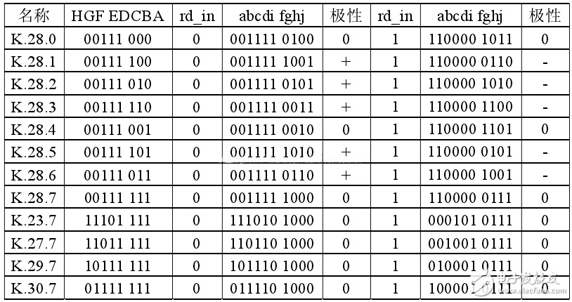
表10:8b/10b 编码K码
1.6.2 D_encode 模块设计
数据字编码共有 256 组,通常将其划分为 3b/4b 编码和 5b/6b 编码分别进行编码,5b/6b 和 3b/4b 编码表如表 4-2 和 4-3 所示。编码结果栏目下,编码结果为中性的只有 1 列,编码结果极性不平衡的,分成了两列,左边一列的编码结果具有正极性,右边一列的编码结果具有负极性。
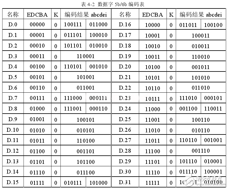
表11:8b/10b 编码D码表
编码表中有两点需要注意:
1、表 4-2 中的 D.7 和表 4-3 中 D.x.3 的编码结果,其编码结果中“1”与“0”的个数相等,它本身是零极性的,但是其编码结果却有两种可能;
2、表 4-3 中输入为 D.x.7 的编码结果可能四种:1110、0001、0111 和 1000,
做出这样规定的目的是为了消除编码结果 eifgh 出现 5 个连续“1”或者“0”的情况。
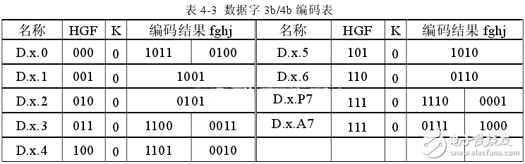
表12:8b/10b 编码D码表
1.6.3 Comma 检测原理
SerDes 接口在发送端将字节信息经过编码和串并转换后,经过信道传输到接收机上,接收机对收到的串行码流进行重定时,并把它们重新恢复成并行的字节数据。Comma 信号就是用来指示字节边界,获取和验证字节同步(ByteSynchronization)的。为了有效达到这个目的,Comma 信号必须具有以下两个特性:它必须是独一无二的,2、相对于字节边界,它能产生一个统一的对齐。在不考虑错误的情况下,Comma 信息不能出现在其他 bit 位上,既不能出现在其他字符中,也不能出现在两个字符之间。符合这两个条件的0011111 和 0011111 被选作是 Comma 信号,包含有 Comma 信号的 K.28.1(001111 1001 或 110000 0110),K.28.5(001111 1010 或 110000 0101),K.28.7(001111 1000 或 110000 0111)被称为 Comma 字符。如果码流中出现两个或者 3 个交叠的 Comma 信号,只有第一个和第三个 Comma 信息会被检测出来。比如出现两个 K.28.7,码流00111110000011111000 中会出现三个 Comma 信号:0011111,1100000 和 0011111,这样只有第一个和第三个 Comma 会被认为是合法的,这符合码流中实际上只有两个 K.28.7 的情况。虽然 K.28.7 不容易出现错码(其他码要错两位才可能变为K.28.7),但是它的跳变密度比较低,不利于时钟数据恢复。所以在实际应用中,一般只使用 K.28.1、K.28.5 作为 Comma 字符,而不使用 K.28.7。
Comma 检测就是检测串行码流中的 Comma 信息,然后把字节边界调整到Comma 信号之前,实现字节边界的对准,为 8b/10b 解码器提供正确的并行输入信号,其功能如图31所示。
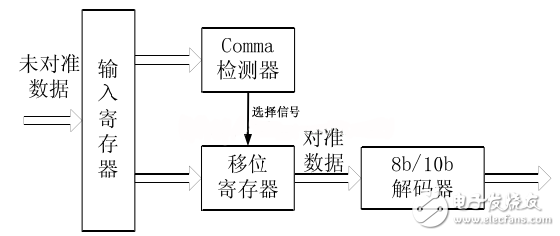
图31:comma检测器
1.7 数据链路层的SystemC仿真
发送器数据链路层的仿真包括数据进入数据链路层后先进行scrambler、然后通过同步字替换模块、再通过8b/10b编码输出,输出的并行数据进入到物理层的SerDes模块,最终输出1bit位宽的数据流。
接收器通过物理层的SerDes模块将输入的1bit数据流数据转为10bit并行的数据,CDR模块将对数据进行恢复,并通过comma码K28.5对输入的数据完成边界的对齐,数据经过8b/10b解码模块后,最终输出到数据通道同步检测模块和帧同步检测模块,通道同步检测模块完成不同数据通道间数据的同步与检测,而帧同步检测模块完成数据帧帧头的识别,同步后的数据将通过descramber模块完成数据的解扰工作,并最终将数据输出到数据传输层,以下是SystemC的仿真图:
上图中,模拟了AD9250的两个AD转换通道,一个通道采样的为数据三角波,一个通道采样的正弦波,而下面的是接收器接收到的数据,该数据的前半段的毛刺是由于系统同步而导致的。
-
数据链路层组帧2014-01-17 0
-
TLP的数据链路层组成与操作2021-01-08 0
-
什么是AFDX发送接收模块?AFDX模块的发送与接收过程是怎样的2021-08-23 0
-
数据链路层.ppt2008-10-23 1271
-
数据链路层的作用2008-07-22 6756
-
数据链路层的功能2008-07-22 3115
-
数据链路层的定义2008-07-22 2437
-
什么是OSI模型数据链路层2010-03-18 2174
-
数据链路层的主要功能2017-11-03 19850
-
数据链路层到底是什么_数据链路层工作原理是怎样的2018-03-14 30107
-
数据链路层常用成纸法有哪些_数据链路层的作用2018-03-14 1736
-
数据链路层设备有哪些2018-03-14 23861
-
一文看懂数据链路层和网络层的区别2018-03-14 70834
-
数据链路层的任务2019-02-27 6814
全部0条评论

快来发表一下你的评论吧 !
