
资料下载


音频编解码器音频串行接口配置
汽车玩家
分享资料个
Introduction
Each system has different requirements when it comes to interfacing to an audio codec ASI. The most common configurations are the master and slave modes. When the audio codec ASI is configured in master mode, its bit clock (BCLK) and word clock (WCLK) pins are output. In slave mode, BCLK and WCLK are inputs to the codec ASI. This relationship might seem straightforward. However, care must be taken when the ASI is configured in slave mode to ensure that the oversampled data that are decimated always fall within the correct target rate time slot.
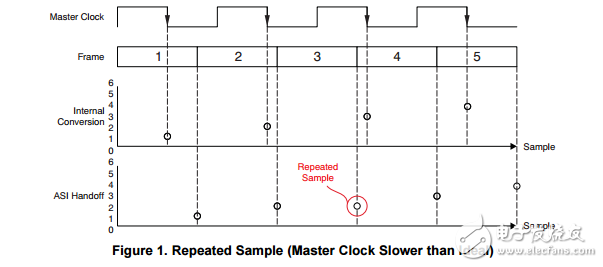
If a master clock is a free-running clock and it is fed to a converter, it will not be frequency-locked to the frame clock (WCLK) of an independent ASI. Any deviation from the ideal will eventually result in a skipped or repeated sample (assuming that the architecture repeats samples)。 For example, if a host processor provides an ideal 48-kHz WCLK with respect to absolute time, its respective ideal master clock could be exactly (128 ● WCLK) = 6.144 MHz. If a master clock from a non-ideal crystal is provided directly to the converter modulator with a 0.001% error, this clock could result in 6.14393856 MHz. Eventually this slower clock will result in a repeated sample out of the ASI bus. Of course, there is no such thing as an ideal master or ASI clocks.
Figure 1 illustrates a simplified case in which a hypothetical analog-to-digital converter (ADC) operating at Nyquist frequency (for simplification purposes) results in a duplicated sample on the ASI bus. In this example, the hypothetical converter ideally hands over its data on the middle of a frame on the falling edge of the master clock. These data should then be ready to be transferred in the beginning of the next frame. As shown in Figure 1, the master clock is actually slower than the ideal. This configuration will eventually drift the clock enough (with respect to the ASI frame) such that there will be a frame that will not receive new data (as shown at the end of frame #3

声明:本文内容及配图由入驻作者撰写或者入驻合作网站授权转载。文章观点仅代表作者本人,不代表电子发烧友网立场。文章及其配图仅供工程师学习之用,如有内容侵权或者其他违规问题,请联系本站处理。 举报投诉
- 相关下载
- 相关文章


