

hmc5883l倾角校准与角度公式
电子常识
描述
HMC5883L作为一个IIC兼容装置,该装置包含一个7-bit串行地址,并支持IIC协议。HMC5883L可以支持标准和快速模式,分别为100kHz和400kHz,但不支持高速模式(Hs)。
要求主机的活动(寄存器读取和写入)优先于内部活动,例如测量,这一优先次序的安排是为了不让主机等待,同时IIC总线占用的事件比必须的时间长。
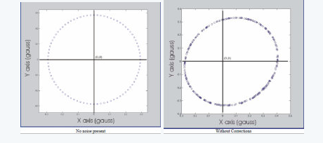
如果磁力计在含有附加的局部磁场的环境中进行操作,磁力计的输出做附加的修正将是必要的。 在没有任何本地磁场的影响下,下图1可以通过旋转设备360°产生的平面 ,图2为引入本地磁场。
方法一。修正的输出可以根据下面的方法来计算:
1)在磁场干扰的条件下进行,数据收集设备被旋转360°。
2)数据进行分析,以产生偏差的偏移和灵敏度的比例因子,以补偿所述干扰。
例子:
从数据中发现的X和Y磁强计的最大输出:
Xmin = -0.284gauss Xmax = +0.402gauss
Ymin = -0.322gauss Ymax = +0.246gauss
从中可以看出X轴的数据,X具有更大的反应,我们设置其比例系数为1
Xs = 1
再计算其他比例系数:
(Xmax - Xmin)
Ys = ————————
(Ymax - Ymin)
对于偏置补偿:
Xb = Xs[1/2(Xmax - Xmin) - Xmax ]
Yb = Ys[1/2(Ymax - Ymin) - Ymax ]
正确的输出:
Xout = Xin*Xs + Xb
Yout = Yin*Ys + Yb
方法二。
1)水平匀速旋转,收集XY轴数据
2)转动器材90度(Z轴)匀速转动以收集Z轴数据
Xoffset = (Xmax + Xmin)/2
Yoffset = (Ymax + Ymin)/2
Zoffset = (Zmax + Zmin)/2
将磁力计读到的裸值减去offset,得到用做角度计算的Heading值
XH = X - Xoffset
YH = Y - Yoffset
ZH = Z - Zoffset
水平测试,得到的方位角 = arctanYH/XH
非水平测试,需要使用加速计进行倾角补偿,先计算出翻滚角Roll和俯仰角Pitch,然后计算Heading值:
XH = x*cos(P)+Y*sin(R)*sin(P)-Z*cos(R)*sin(p)
YH = Y*cos(R)+Z*sin(R)
关于为什么设置偏置,请参考以下文章:
ST集成传感器方案实现电子罗盘功能:http://www.dzsc.com/data/html/2010-11-29/87454.html
HMC5883L常见问题解答:http://blog.sina.com.cn/s/blog_402c071e0102v8gj.html
这里我采用了上方的简单方法,来计算一个 offsetX, offsetY, offsetZ,然后减去这个偏移量,得到了正确的结果。下方是代码。下方我做了一个处理(诸如:mag.x*0.2 + magRange[0]*0.8)。是因为偶尔mag.x mag.y mag.z 会出现一个异常的值,使得计算的offsetX offsetY offsetZ不准,所以加了这个滤波处理。
static float magRange[6] = {1.0,-1.0,1.0,-1.0,1.0,-1.0};// magRange[0] 对应X最小,magRange[1] 对应X最大
// Magnetometer not yet used more then for logging.
// 磁力计尚未使用到,仅仅只是 log 记录下来。
imu9Read(&gyro, &acc, &mag);
if(magRange[0] 》 mag.x) magRange[0] = mag.x*0.2 + magRange[0]*0.8; // x min
if(magRange[1] 《 mag.x) magRange[1] = mag.x*0.2 + magRange[1]*0.8; // x max
if(magRange[2] 》 mag.y) magRange[2] = mag.y*0.2 + magRange[2]*0.8;
if(magRange[3] 《 mag.y) magRange[3] = mag.y*0.2 + magRange[3]*0.8;
if(magRange[4] 》 mag.z) magRange[4] = mag.z*0.2 + magRange[4]*0.8; // z min
if(magRange[5] 《 mag.z) magRange[5] = mag.z*0.2 + magRange[5]*0.8; // z max
magOffset[0] = (magRange[0]+magRange[1])/2.0;
magOffset[1] = (magRange[2]+magRange[3])/2.0;
magOffset[2] = (magRange[4]+magRange[5])/2.0;
mag.x -= magOffset[0];
mag.y -= magOffset[1];
mag.z -= magOffset[2];
自我检测也比较重要。通过HMC5883l芯片提供的自我检测功能,进行自我检测,然后找到一个比例因子。将传感器的检测值乘以这个比例因子,就可以修正磁场。我在代码中没有使用。相关的详细资料请看如下英文。
相关源代码,可以参考 Crazyflie firmware中的 bool hmc5883lSelfTest() 函数。
SELF TEST OPERATION
To check the HMC5883L for proper operation, a self test feature in incorporated in which the sensor offset straps are excited to create a nominal field strength (bias field) to be measured. To implement self test, the least significant bits (MS1 and MS0) of configuration register A are changed from 00 to 01 (positive bias) or 10 (negetive bias), e.g. 0x11 or 0x12.
Then, by placing the mode register into single-measurement mode (0x01), two data acquisition cycles will be made on each magnetic vector. The first acquisition will be a set pulse followed shortly by measurement data of the external field. The second acquisition will have the offset strap excited (about 10 mA) in the positive bias mode for X, Y, and Z axes to create about a ±1.1 gauss self test field plus the external field. The first acquisition values will be subtracted from the second acquisition, and the net measurement will be placed into the data output registers.
Since self test adds ~1.1 Gauss additional field to the existing field strength, using a reduced gain setting prevents sensor from being saturated and data registers overflowed. For example, if the configuration register B is set to 0x60 (Gain=3), values around +766 LSB (1.16 Ga * 660 LSB/Ga) will be placed in the X and Y data output registers and around +713 (1.08 Ga * 660 LSB/Ga) will be placed in Z data output register. To leave the self test mode, change MS1 and MS0 bit of the configuration register A back to 00 (Normal Measurement Mode), e.g. 0x10.
比例因子校准
SCALE FACTOR CALIBRATION
Using the self test method described above, the user can scale sensors’ sensitivity to match each other. Since placing device in positive bias mode (or alternatively negative bias mode) applies a known artificial field on all three axes, the resulting ADC measurements in data output registers can be used to scale the sensors. For example, if the expected self test value for X-axis is 766 and the actual value is 750 then a scale factor of (766/750) should be multiplied to all future readings of X-axis. Doing so for all three axes will ensure their sensitivity are well matched.
The built-in self test can also be used to periodically compensate the scaling errors due to temperature variations. A compensation factor can be found by comparing the self test outputs with the ones obtained at a known temperature. For example, if the self test output is 750 at room temperature and 700 at the current temperature then a compensation factor of (750/700) should be applied to all current magnetic readings. A temperature sensor is not required using this method.
Crazyflie firmware中的 bool hmc5883lSelfTest() 函数代码如下,仅供参考:(函数中的各种定义这里未给出)
bool hmc5883lSelfTest()
{
bool testStatus = TRUE;
int16_t mxp, myp, mzp; // positive magnetometer measurements
int16_t mxn, myn, mzn; // negative magnetometer measurements
struct
{
uint8_t configA;
uint8_t configB;
uint8_t mode;
} regSave;
// Save register values
if (i2cdevRead(I2Cx, devAddr, HMC5883L_RA_CONFIG_A, sizeof(regSave), (uint8_t *)®Save) == FALSE)
{
// TODO: error handling
return FALSE;
}
// Set gain (sensitivity)
hmc5883lSetGain(HMC5883L_ST_GAIN);
// Write CONFIG_A register and do positive test
i2cdevWriteByte(I2Cx, devAddr, HMC5883L_RA_CONFIG_A,
(HMC5883L_AVERAGING_1 《《 (HMC5883L_CRA_AVERAGE_BIT - HMC5883L_CRA_AVERAGE_LENGTH + 1)) |
(HMC5883L_RATE_15 《《 (HMC5883L_CRA_RATE_BIT - HMC5883L_CRA_RATE_LENGTH + 1)) |
(HMC5883L_BIAS_POSITIVE 《《 (HMC5883L_CRA_BIAS_BIT - HMC5883L_CRA_BIAS_LENGTH + 1)));
hmc5883lSetMode(HMC5883L_MODE_SINGLE);
vTaskDelay(M2T(HMC5883L_ST_DELAY_MS));
hmc5883lGetHeading(&mxp, &myp, &mzp);
// Write CONFIG_A register and do negative test
i2cdevWriteByte(I2Cx, devAddr, HMC5883L_RA_CONFIG_A,
(HMC5883L_AVERAGING_1 《《 (HMC5883L_CRA_AVERAGE_BIT - HMC5883L_CRA_AVERAGE_LENGTH + 1)) |
(HMC5883L_RATE_15 《《 (HMC5883L_CRA_RATE_BIT - HMC5883L_CRA_RATE_LENGTH + 1)) |
(HMC5883L_BIAS_NEGATIVE 《《 (HMC5883L_CRA_BIAS_BIT - HMC5883L_CRA_BIAS_LENGTH + 1)));
hmc5883lSetMode(HMC5883L_MODE_SINGLE);
vTaskDelay(M2T(HMC5883L_ST_DELAY_MS));
hmc5883lGetHeading(&mxn, &myn, &mzn);
if (hmc5883lEvaluateSelfTest(HMC5883L_ST_X_MIN, HMC5883L_ST_X_MAX, mxp, “pos X”) &&
hmc5883lEvaluateSelfTest(HMC5883L_ST_Y_MIN, HMC5883L_ST_Y_MAX, myp, “pos Y”) &&
hmc5883lEvaluateSelfTest(HMC5883L_ST_Z_MIN, HMC5883L_ST_Z_MAX, mzp, “pos Z”) &&
hmc5883lEvaluateSelfTest(-HMC5883L_ST_X_MAX, -HMC5883L_ST_X_MIN, mxn, “neg X”) &&
hmc5883lEvaluateSelfTest(-HMC5883L_ST_Y_MAX, -HMC5883L_ST_Y_MIN, myn, “neg Y”) &&
hmc5883lEvaluateSelfTest(-HMC5883L_ST_Z_MAX, -HMC5883L_ST_Z_MIN, mzn, “neg Z”))
{
DEBUG_PRINT(“Self test [OK]。\n”);
}
else
{
testStatus = FALSE;
}
// Restore registers
if (i2cdevWrite(I2Cx, devAddr, HMC5883L_RA_CONFIG_A, sizeof(regSave), (uint8_t *)®Save) == FALSE)
{
// TODO: error handling
return FALSE;
}
return testStatus;
}
-
Protues中HMC5883L寻找2012-11-27 0
-
有谁用STM32编过HMC5883L的程序啊?2014-06-28 0
-
HMC5883L2016-04-16 0
-
HMC5883L常见问题解答2016-08-17 0
-
基于HMC5883L的电子指南针2016-09-10 0
-
电子罗盘HMC5883L DRDY引脚角度有问题2019-05-06 0
-
请问怎么进行HMC5883L数据的读取2019-05-08 0
-
MPU6050和HMC5883L结合做动作识别有什么其他动作?2019-05-13 0
-
如何处理磁力计HMC5883L获取的三轴数据?2019-07-25 0
-
请问MPU6050,HMC5883L,ADXL345之间我该选择哪个?2019-07-31 0
-
Noob使用ESP8266校准HMC5883L一直报错是怎么回事?2023-06-01 0
-
HMC5883L中文2016-12-13 994
-
hmc5883l三轴电子罗盘传感器连接arduino2018-03-08 18075
-
hmc5883l的特点及优点_HMC5883L磁力计校准方法2018-03-08 15697
-
HMC5883L应用说明2018-03-08 27627
全部0条评论

快来发表一下你的评论吧 !
