

ZSSC4165 SSC通信板 ZSSC416xKIT系列的主要特性
汽车电子
描述
IDT公司的ZSSC416x/ZSSC417x系列是用于高精度放大和差分桥传感器信号修正的CMOS集成电路,模拟放大范围从150到200,可调理所有的电阻桥和电压源类传感器如热电偶,失调,灵敏度,温漂和非线性数字补偿由16位RISC MCU来实现,而校准系数和配置数据存储在器件中的非易式存储器(NVM),具有SENT或I2C输出,主要用在汽车电子.本文介绍了ZSSC4165主要特性,框图,应用电路以及ZSSC416xKIT系列评估板主要特性和SSC通信板主要特性和优势与电路图.
IDT’s ZSSC416x/ZSSC417x is a family of CMOSintegrated circuits for highly accurate amplificationand sensor-specific correction of differential bridgesensor signals. Featuring a maximum analog pre-amplificationin the range of 150 to 200, this productis adjustable to nearly all resistive bridges as well asvoltage source sensor types; e.g.,thermocouples.
Digital compensation of offset, sensitivity, temperaturedrift, and nonlinearity is accomplished with a16-bit RISC microcontroller. Calibration coefficientsand configuration data are stored in the ZSSC416x/ZSSC417x non-volatile memory (NVM), which isreliable in automotive applications.
Measured values can be read via a digital SENT orI2C™* interface. The SENT interface enables transmissionof sensor data via its fast channel as well assupplementary data via its“slow”Serial Data Message(SDM) channel using only one output pin. Endof-line calibration is supported via an I2C™ interfaceor via a One-Wire Interface (OWI) through the dataoutput pin (DOUT). The ZSSC416x/ZSSC417x andthe calibration equipment communicate digitally,so the noise sensitivity is greatly reduced. Digitalcalibration helps keep assembly cost low as no trimming by external devices or lasers is needed.
The ZSSC416x/ZSSC417x is optimized for automotiveenvironments by overvoltage and reversepolarity protection circuitry, excellent electromagneticcompatibility, and multiple diagnostic features.
ZSSC4165主要特性:
· Differential sensor bridge or voltage source inputs
· Internal or external temperature sensors, selectablefor conditioning of sensor input signals ortemperature output
· Digital compensation of offset, gain, and higherorder nonlinearity as well as temperaturecoefficients of measured sensor input signals
· Operating temperature range: -40°C to 150°C
· Accuracy: ±0.25% FSO @ -40°C to 125°C
· NVM memory for configuration data, user configurablemeasurement and conditioning function,and user-selected data
ZSSC4165主要优势:
· SENT output option based on SAE J2716 Rev 3.0standard using fast and SDM data channels
· Supports output of one or more sensor signalsand product identification via a single SENT
interface connection
· Configurable for nearly all resistive bridge sensors
· One-pass end-of-line calibration algorithmminimizes production costs
· No external trimming or components required
· I²C™ interface option
Available Support
· Evaluation Kit
· Application Notes
· Calculation Tools
Physical Characteristics
· Supply voltage: 4.75V to 5.25V
· Protection up to +/-18V
· Input span: 1 to 800 mV/V
· Analog-to-digital (ADC) resolution: configurablefrom 12 to 16 bit
· Large sensor offset correction using digitalzooming with 14 to 18 bit resolution
· Output resolution: 12-bit via SENT interface; up to15-bit plus a sign bit for OWI or I2C™ interface
· Package: 4x4mm QFN24 or die
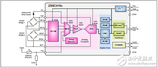
图1.ZSSC416x系列框图
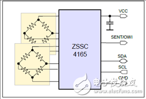
图2. ZSSC416x系列双桥应用基本电路图
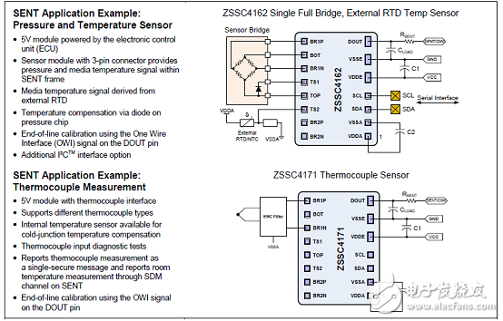
图3. ZSSC416x SENT应用框图
ZSSC416xKIT系列评估板
The ZSSC416xKIT Evaluation Kit provides the hardware needed for configuration, calibration and evaluation of the ZSSC4161, ZSSC4162 and ZSSC4165 Sensor Signal Conditioner (SSC) ICs. The user’s PC can communicate with the ZSSC416x IC mounted on the ZSSC415x/6x/7x SSC Evaluation Board via the SSC Communication Board through a USB connection. The Evaluation Kit Software is available on-line for free download.
The Evaluation Board can connect to the user’s sensor or to the SSC Sensor Replacement Board (SRB). The SRB provides a replacement for an actual sensor and can be used for the first step of calibration or a dry-run calibration. On the SRB, the simulated resistive sensor signal is controlled by a potentiometer. The kit also includes three small populated test PCBs: each includes a ZSSC4161, ZSSC4162, or ZSSC4165 QFN sample and the required external components already mounted for facilitating user prototypes.
ZSSC416xKIT系列评估板主要特性:
ZSSC415x/6x/7x Evaluation Board with one sample mounted
SSC Communication Board
SSC Sensor Replacement Board
USB Cable
ZSSC4161_QFN_PCB
ZSSC4162_QFN_PCB
ZSSC4165_QFN_PCB
5 additional samples each of ZSSC4161, ZSSC4162 and ZSSC4165
Vacuum suction pen
SSC通信板
The SSC Communication Board is included in IDT’s modular SSC Evaluation Kits for select sensor signal conditioner (SSC) ICs. It is also part of the modular SSC Mass Calibration System for SSC ICs. It provides communication between the user’s computer and the SSC IC mounted on the SSC Evaluation Board, the user’s module, or a mass calibration reference board connected to the mass calibration board. It can be ordered separately.
The SSC Modular Evaluation Kit provides hardware and software for a very simple and intuitive method of evaluating IDT’s sensor signal conditioner (SSC) ICs. For the evaluation of different SSC ICs, only the IC-specific SSC Evaluation Board and software are needed; the other parts of the evaluation hardware (SSC Communication Board and SSC Sensor Replacement Board) are typically the same.
The SSC Communication Board V4.1* (SSC CB) can provide the power supply for the evaluation hardware and handle the communication with a PC via a USB interface. To prevent malfunctioning or damage, a galvanic isolation to the PC’s USB port is established on board via digital isolators for the information lines and an isolated DC/DC converter for the power line. It is also possible to supply the Communication Board and connected kit boards or user modules by an external power line (12V typical) via the KL1 screw terminal on the SSC CB. It is also possible to supply low voltage devices with a fixed 1.8 or 3.3 VDC internal voltage. Alternatively the connected application could be supplied via the KL2 screw terminal with a voltage of 1.0 to 3.6 VDC.
A USB-UART device transfers all signals to the stan-dardized USB port of the user’s PC. Its UART interface is connected via digital isolators with the UART of an on-board microcontroller that controls all functions of the Evaluation Kit and of the SSC IC to be evaluated. Its software allows direct communi-cation with the SSC IC via several interface options depending on the IC: I2C™†, SPI, ZACwire™ (One-Wire Interface (OWI)), LIN via a discrete level shifter, or SENT. The microcontroller also controls the power lines (5VDC and two lines for 12VDC) by driv-ing several electronic switches. The microcontroller displays the status of communication via LEDs.
An on-board dual header strip enables access to all signal and power lines. This allows a simple signal check; e.g., by a digital oscilloscope, a multimeter, or a connection with user-specific hardware.
SSC通信板主要特性:
• Interface fully compatible with USB 2.0
• “Plug & play” capability
• Power for the Evaluation Kit provided by the USB port or an external power supply as selected with a jumper setting
• Internal generation of all required voltage levels: 5 VDC and 12 VDC
• On-board galvanic isolation between PC and evaluation hardware
• Access to all digital communication lines of the IDT SSC IC being evaluated
SSC通信板优势:
• PC-controlled configuration and calibration via USB interface – simple, low cost
• Standard communication board for all IC types in IDT’s SSC product family
• USB port driver included in the Evaluation Kit setup software – simple installation
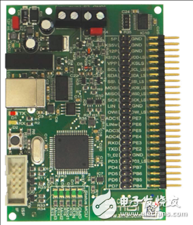
图4.SSC通信板外形图
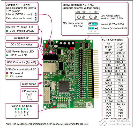
图5.SSC通信板概述图
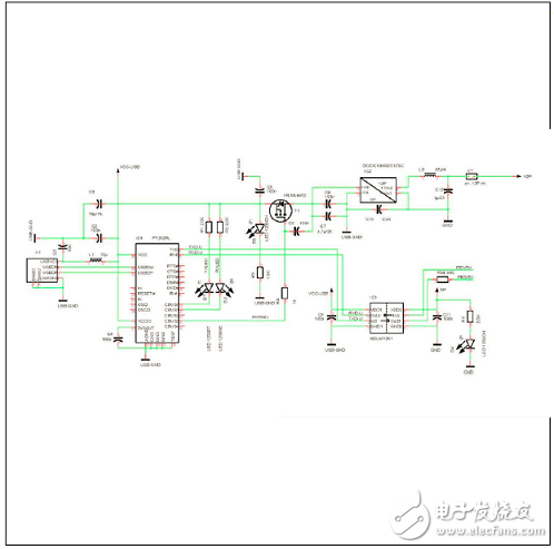
图6.SSC通信板电路图(1):USB接口
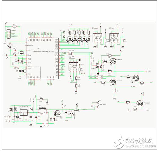
图7.SSC通信板电路图(2):MCU
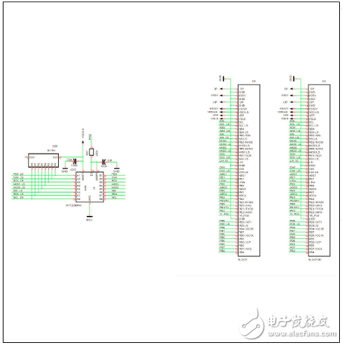
图8.SSC通信板电路图(3):电平转换和50引脚连接器
-
ZSSC3123 数据表2023-01-13 126
-
ZSSC41xx SSC 评估板 Reference Guide2023-03-15 205
-
ZSSC3218 数据表2023-03-23 103
-
ZSSC3135 数据表2023-03-24 109
-
ZSSC3131 数据表2023-03-24 109
-
ZSSC3281 数据表2023-06-30 93
-
ZSSC3240 数据表2023-07-04 115
-
ZSSC3018 数据表2023-07-04 87
-
ZSSC4151 数据表2023-07-10 125
-
ZSSC3136 数据表2023-07-11 82
-
ZSSC5101 数据表2023-07-11 97
-
ZSSC3015数据表2023-07-11 94
全部0条评论

快来发表一下你的评论吧 !
