

AWR1243主要特性 功能_PCB设计图
汽车电子
描述
TI公司的AWR1243是单片77GHz和79GHz频率调制连续波(FMCW)收发器,具有基于分数N PLL的超精密啁啾引擎,简化了汽车雷达传感器在76-81GHz的实现方案.采用低功耗45nm RFCMOS工艺,单片实现了内置PLL和A2D转换器的3TX,4RX系统.TX发送功率12dBm,RX噪音15dB (76-77GHz), 16dB(77-81GHz),1MHz时的相位噪音–94 dBc/Hz (76-77 GHz),–91 dBc/Hz (77 - 81 GHz),内置了校准和自测试等功能.主要用在自动高速公路驾驶,自动紧急刹车和自适应巡航控制.本文介绍了AWR1243主要特性,功能框图,短中远距离雷达框图,参考电路,以及AWR1443 BoosterPack™评估板主要特性,框图,电路图,材料清单和PCB设计图.
The AWR1243 device is an integrated single-chip FMCW transceiver capable of operation in the 76- to 81-GHz band. The device enables unprecedented levels of integration in an extremely small form factor. AWR1243 is an ideal solution for low power, self-monitored, ultra-accurate radar systems in the automotive space.
The AWR1243 device is a self-contained FMCW transceiver single-chip solution that simplifies the implementation of Automotive Radar sensors in the band of 76 to 81 GHz. It is built on TI’s low-power 45-nm RFCMOS process, which enables a monolithic implementation of a 3TX, 4RX system with built-in PLL and A2D converters. Simple programming model changes can enable a wide variety of sensor implementation (Short, Mid, Long) with the possibility of dynamic reconfiguration for implementing a multimode sensor. Additionally, the device is provided as a complete platform solution including reference hardware design, software drivers, sample configurations, API guide, and user documentation.
AWR1243主要特性:
FMCW Transceiver
Integrated PLL, Transmitter, Receiver, Baseband, and A2D
76- to 81-GHz Coverage With 4 GHz Available Bandwidth
Four Receive Channels
Three Transmit Channels (Two Can be Used Simultaneously)
Ultra-Accurate Chirp Engine Based on Fractional-N PLL
TX Power: 12 dBm
RX Noise Figure:
15 dB (76 to 77 GHz)
16 dB (77 to 81 GHz)
Phase Noise at 1 MHz:
–94 dBc/Hz (76 to 77 GHz)
–91 dBc/Hz (77 to 81 GHz)
Built-in Calibration and Self-Test
Built-in Firmware (ROM)
Self-calibrating System Across Frequency and Temperature
Host Interface
Control Interface With External Processor Over SPI
Data Interface With External Processor Over MIPI D-PHY and CSI2 V1.1
Interrupts for Fault Reporting
ASIL B Capable
AECQ100 Qualified
AWR1243 Advanced Features
Embedded Self-monitoring With No Host Processor Involvement
Complex Baseband Architecture
Option of Cascading Multiple Devices to Increase Channel Count
Embedded Interference Detection Capability
Power Management
Built-in LDO Network for Enhanced PSRR
I/Os Support Dual Voltage 3.3 V/1.8 V
Clock Source
40.0-MHz Crystal With Internal Oscillator
Supports External Oscillator at 40 and 50 MHz
Easy Hardware Design
0.65-mm Pitch, 161-Pin 10.4 mm × 10.4 mm Flip Chip BGA Package for Easy Assembly and Low-Cost PCB Design
Small Solution Size
Supports Automotive Temperature Operating Range
AWR1243应用:
• Automated Highway Driving
• Automatic Emergency Braking
• Adaptive Cruise Control
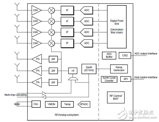
图1.AWR1243功能框图
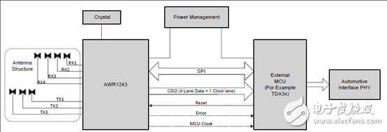
图2.AWR1243短中远距离雷达框图
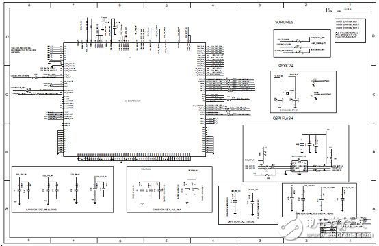
图3.AWR1243参考电路图
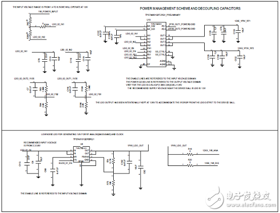
图4.AWR1243低噪音LDO电路图
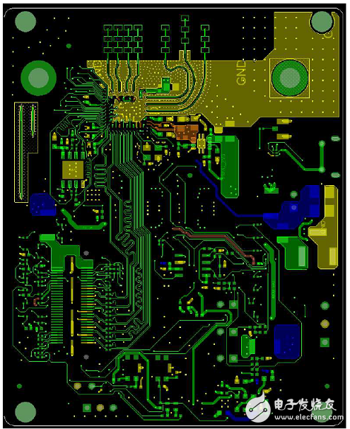
图5.AWR1243参考电路PCB布局图(顶层)
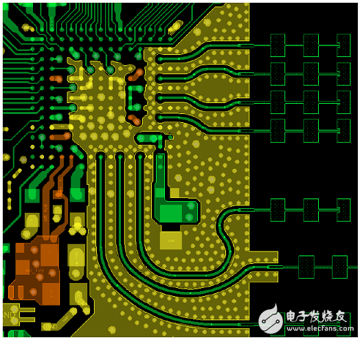
图6.AWR1243参考电路PCB布局图(顶层放大图)
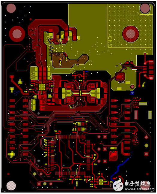
图7.AWR1243参考电路PCB布局图(底层)
AWR1443 BoosterPack™评估板
The AWR1443 BoosterPack™ is an easy-to-use evaluation board for the single-chip AWR1443 mmWavesensing device from TI, with direct connectivity to the TI MCU LaunchPad™ ecosystem. The evaluationboard contains everything needed to start developing on a low-power ARM®-R4F controller. Theevaluation board includes onboard emulation for programming and debugging, onboard buttons, andLEDs, for quick integration of a simple user interface. The standard 20-pin BoosterPack headers make the evaluation board compatible with a wide variety of TI MCU LaunchPads and enables easy prototyping.
The AWR1243 BoosterPack is an evaluation board for the AWR1243 mmWave high-performance frontend. The evaluation platform enables raw capture of ADC data from the front end and evaluation of RFperformance.
AWR1443 BoosterPack™评估板主要特性:
• 40-pin LaunchPad standard that leverages the LaunchPad ecosystem
• XDS110-based JTAG emulation with serial port, for onboard QSPI flash programming (for AWR1443)
• Backchannel UART through USB to PC, for logging purposes
• Onboard antenna
• 60-pin high density (HD) connector, for raw ADC data over CSI, or the high-speed debug interface
• Onboard CAN transceiver (for AWR1443)
• One button and two LEDs, for user interaction
• 5-V power jack, to power the board
AWR1443 BoosterPack™评估板包括:
• AWR1443BOOST or AWR1243BOOST
• Mounting brackets, screws, and nuts, to allow placing the PCB vertical
• Mirco USB cable to connect to the PC
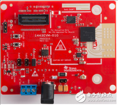
图8.AWR1443 BoosterPack™评估板外形图
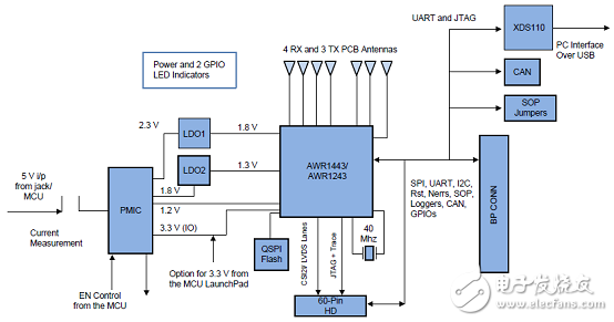
图9.AWR1443 BoosterPack™评估板框图
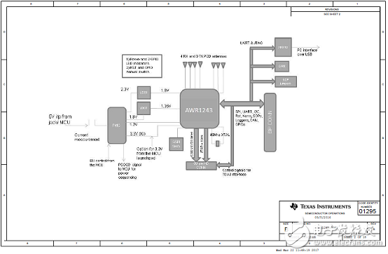
图10.AWR1443 BoosterPack™评估板电路图(1)
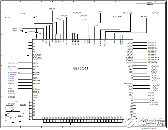
图11.AWR1443 BoosterPack™评估板电路图(2)
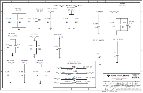
图12.AWR1443 BoosterPack™评估板电路图(3)
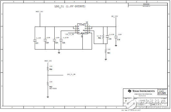
图13.AWR1443 BoosterPack™评估板电路图(4)
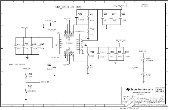
图14.AWR1443 BoosterPack™评估板电路图(5)
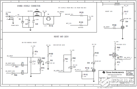
图15.AWR1443 BoosterPack™评估板电路图(6)
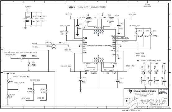
图16.AWR1443 BoosterPack™评估板电路图(7)
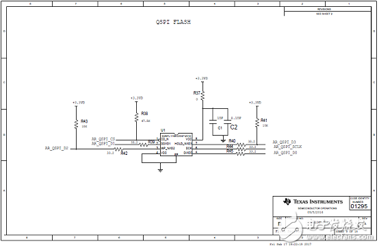
图17.AWR1443 BoosterPack™评估板电路图(8)
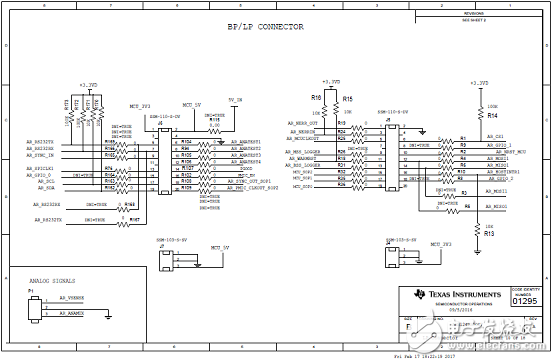
图18.AWR1443 BoosterPack™评估板电路图(9)
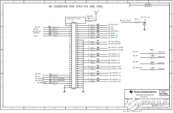
图19.AWR1443 BoosterPack™评估板电路图(10)
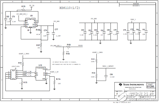
图20.AWR1443 BoosterPack™评估板电路图(11)

图21.AWR1443 BoosterPack™评估板电路图(12)
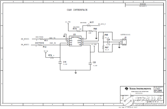
图22.AWR1443 BoosterPack™评估板电路图(13)
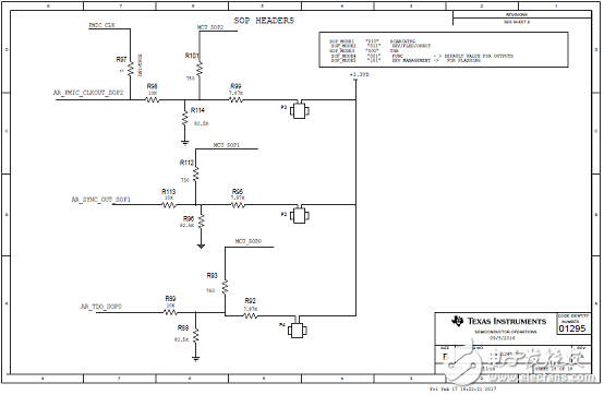
图23.AWR1443 BoosterPack™评估板电路图(14)
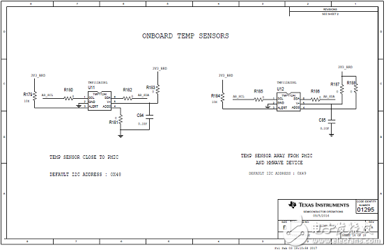
图24.AWR1443 BoosterPack™评估板电路图(15)
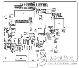
图25.AWR1443 BoosterPack™评估板PCB设计图(1)
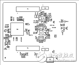
图26.AWR1443 BoosterPack™评估板PCB设计图(2)
-
关于pcb设计图查看软件的2016-05-10 0
-
请问有人能根据我的描述意图画出大致的电路图或者PCB设计图吗?2018-01-12 0
-
ZigBee模块CC2530天线PCB设计图2016-05-10 3144
-
TIAWR1243汽车77和79GHz FMCW收发器解决方案2017-06-06 1803
-
AWR和Zuken发布PCB射频验证流程2017-12-07 458
-
PAC1934主要特性 PAC1934评估板ADM00805特性2018-04-03 2530
-
awr1243数据手册2018-04-18 1086
-
iMOTION™ IMC100系列主要特性的介绍2018-05-16 3133
-
MAX14483优势和特性/应用电路_评估板MAX14483 EVK电路图及PCB设计图2018-06-16 5143
-
一文详解IDP2303的主要特性/应用电路图及PCB设计图2018-06-16 18971
-
AD8452主要特性_框图以及应用电路2019-05-11 7267
-
CC1352P主要特性以及pcb电路图2019-04-05 6831
-
MAX40056主要特性以及应用电路2019-04-05 5383
-
pcb设计图及原理图2022-12-12 889
全部0条评论

快来发表一下你的评论吧 !
