

DRV8802-Q1主要特性 功能框图和应用电路
汽车电子
描述
TI公司的DRV8802-Q1是汽车电子1.6A双路无刷DC马达驱动器,具有两个H桥驱动器.输出驱动器包括可配置成H桥的N沟功率MOSFET,每和H桥提供1.1A RMS或峰值电流1.6A,满足AEC-Q100规范,工作温度–40℃到125℃,主要用在汽车HVAC,汽车阀门和汽车娱乐系统.本文介绍了DRV8802-Q1主要特性,功能框图和应用电路,以及参考设计TIDA-01357主要特性,框图,电路图,材料清单和PCB设计图和合成图.
The DRV8802-Q1 device provides an integrated motor driver solution for automotive applications. The device has two H-bridge drivers, and is intended to drive DC motors. The output driver block for each consists of N-channel power MOSFET’s configured as H-bridges to drive the motor windings. The DRV8802-Q1 device can supply up to 1.6-A peak or 1.1-A RMS output current (with proper heatsinking at 24 V and 25℃) per H-bridge.
A simple parallel digital control interface is compatible with industry-standard devices. Decay mode is programmable to allow braking or coasting of the motor when disabled.Internal shutdown functions are provided for over current protection, short circuit protection, under voltage lockout and overtemperature. The DRV8802-Q1 device is available in a 28-pin HTSSOP package with PowerPAD (Eco-friendly: RoHS & no Sb/Br).
DRV8802-Q1主要特性:
Qualified for Automotive Applications
AEC-Q100 Qualified With the Following Results
Device Temperature Grade 1: –40℃ to 125℃ Ambient Operating Temperature
Device HBM ESD Classification Level 2
Device CDM ESD Classification Level C4B
Dual H-Bridge Current-Control Motor Driver
Drives Two DC Motors
Brake Mode
Two-Bit Winding Current Control Allows Up to 4 Current Levels
Low MOSFET On-Resistance
1.6-A Maximum Drive Current at 24 V, 25℃
Built-In 3.3-V Reference Output
Industry Standard Parallel Digital Control Interface
8-V to 45-V Operating Supply Voltage Range
Thermally Enhanced Surface Mount Package
DRV8802-Q1应用:
• Automotive HVAC
• Automotive Valves
• Automotive Infotainment
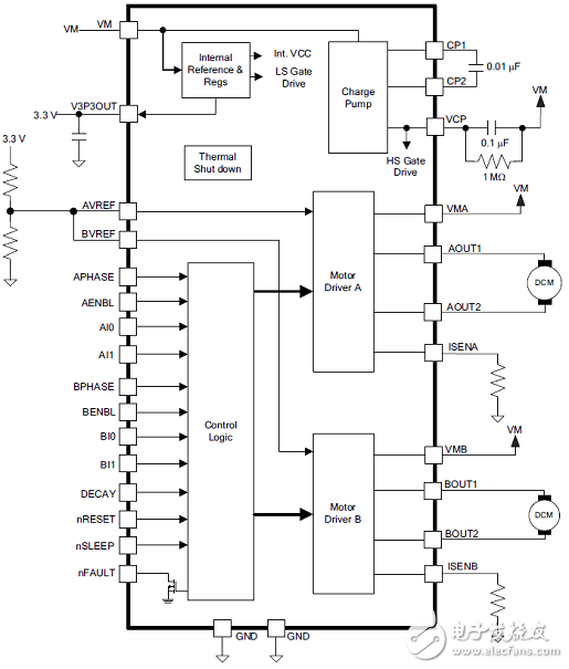
图1.DRV8802-Q1功能框图

图2.DRV8802-Q1应用电路图
参考设计TIDA-01357
The TIDA-01357 TI Design offers a solution for DCmotors by using the DRV8802-Q1 device to controlautomotive HVAC flap actuators or dampers. Thisdesign demonstrates a cost-effective motor driversolution for six flap actuator where all six motors canbe driven simultaneously with an output current up to0.4 A per motor. This reference design maintains asmall solution size and low quiescent current inaddition to offering reverse battery and load dumpprotection, all of which are highlighted in this guide.brushed-DC motors or stepper motors. This TI Design offers a solution for DC-motor-based flap actuators.
The end goal is to develop a cost-effective motor driver solution for six-flap actuators that can be drivensimultaneously. This design includes protection features against load dump conditions and reverse batteryconditions and maintains a small solution size and low quiescent current at the same time.
The TIDA-01357 has been designed with a focus on the following points:
• Simultaneously driving six brushed-DC motors for a flap actuator
• Capability to survive reverse battery and load dump conditions (12-V system)
• Low quiescent current
• Compact design and high performance
• Use of a diagnostics feature (output short detect)
参考设计TIDA-01357主要特性:
• Survives Voltages up to 45 V
• Withstands Reverse Battery Conditions and LoadDump Conditions (12-V System)
• Three-Chip Solution to Drive up to Six MotorsSimultaneously (Two DC Motors per IC)
• Compact Layout; Does Not Require External FETs
• Low Quiescent Current
• Components Selected for Automotive Temperatureand Quality
参考设计TIDA-01357应用:
• Automotive HVAC Flap Actuator and DamperMotor Drive
• Automotive HVAC Intake Air-Flap Motor Drive
参考设计TIDA-01357电特性:
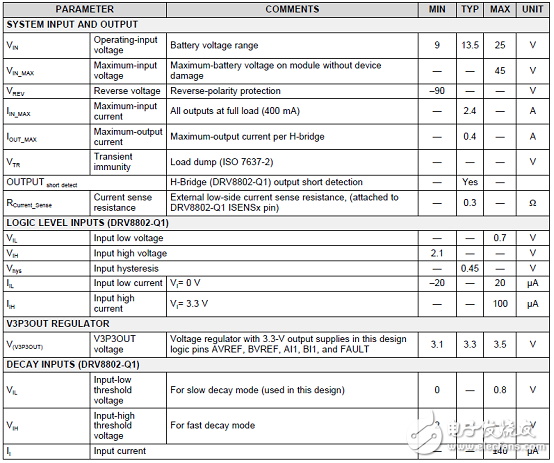
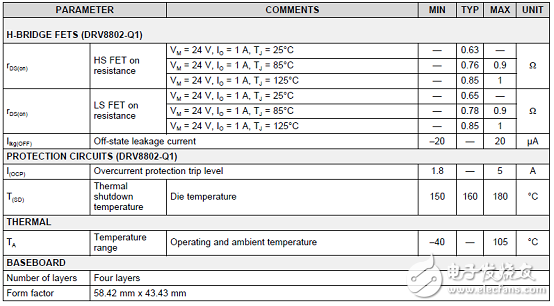
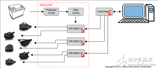
图3.参考设计TIDA-01357框图
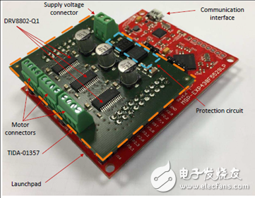
图4. LaunchPad™可发板和TIDA-01357外形图
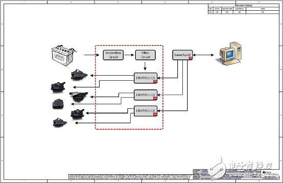
图5.参考设计TIDA-01357电路图(1)
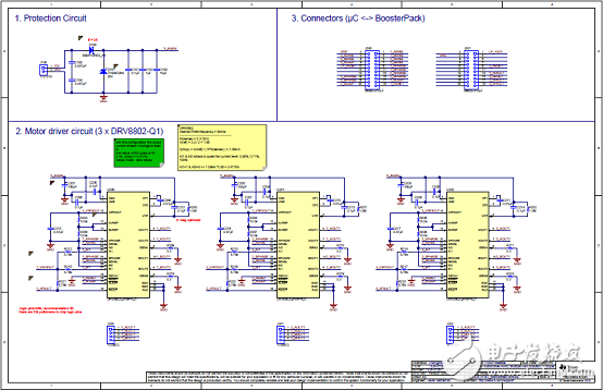
图6.参考设计TIDA-01357电路图(2)
参考设计TIDA-01357材料清单:
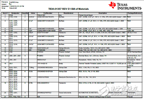
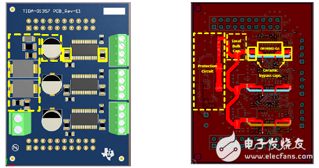
图7.参考设计TIDA-01357 PCB合成图.左:顶层元件布局;右:顶层走线布局
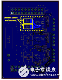
图8.参考设计TIDA-01357 PCB合成图:底层走线布局
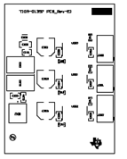
图9.参考设计TIDA-01357 PCB设计图(1)
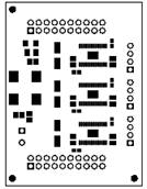
图10.参考设计TIDA-01357 PCB设计图(2)
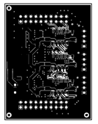
图11.参考设计TIDA-01357 PCB设计图(3)
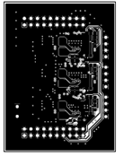
图12.参考设计TIDA-01357 PCB设计图(4)
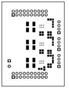
图13.参考设计TIDA-01357 PCB设计图(5)
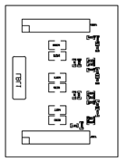
图14.参考设计TIDA-01357 PCB设计图(6)
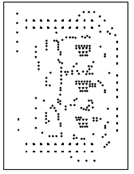
图15.参考设计TIDA-01357 PCB设计图(7)
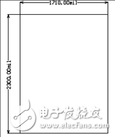
图16.参考设计TIDA-01357 PCB设计图(8):外形尺寸
-
RT8802A应用电路图2010-03-22 6441
-
RT8802A的特性及应用2010-03-22 2778
-
IDT无线充电P9038发送器方案(P9038主要特性,功能框图及应用电路)2017-12-13 3950
-
DRV10983-Q1主要特性_功能框图2018-04-13 5342
-
DRV10987及评估模块DRV10987 EVM主要特性、电路图2018-04-13 4385
-
三相马达驱动用的栅极驱动器DRV8305-Q1的主要特性2018-04-27 9007
-
一文解析TPS657051的特性_功能_应用电路2018-05-12 5581
-
ad8367中文资料汇总(ad8367引脚图及功能框图_特性参数及应用电路)2018-05-16 33778
-
TI DRV8833马达驱动解决方案2018-05-29 3329
-
DRV8802-Q1 DRV8802-Q1 汽车类直流电机驱动器 IC2018-10-16 239
-
AD8452主要特性_框图以及应用电路2019-05-11 7267
-
NCP51705主要特性_内部框图以及应用电路2019-05-11 4010
-
ISO224主要特性以及应用电路2019-04-05 10295
-
MAX40056主要特性以及应用电路2019-04-05 5383
-
集成式三相电动机驱动器DRV8312/32的性能特点及应用电路2021-03-30 6368
全部0条评论

快来发表一下你的评论吧 !
