

TI公司三个高精度半桥驱动器_TIDA-01330设计图
汽车电子
描述
TI公司的DRV8305-Q1是三相马达驱动的栅极驱动集成电路,提供三个高精度半桥驱动器,每个可驱动高边和低边N-MOSFET,电荷泵驱动器支持100%占空比,满足汽车应用的AEC-Q100规范,4.4V-45V工作电压,峰值栅极驱动电流1.25A和1A,主要用在三相BLDC和PMSM马达,汽车油泵和水泵,汽车风扇和鼓风机.本文介绍了DRV8305-Q1主要特性,框图,典型应用电路以及汽车两轴电动座椅驱动参考设计TIDA-01330主要特性,框图,电路图,材料清单和PCB设计图.
The DRV8305-Q1 device is a gate driver IC for threephasemotor-drive applications. The device providesthree high-accuracy half-bridge drivers, each capableof driving a high-side and low-side N-channelMOSFET. A charge pump driver supports 100% dutycycle and low-voltage operation for cold cranksituations. The device can tolerate load dumpvoltages up to 45-V.
The DRV8305-Q1 device includes three bidirectionalcurrent-shunt amplifiers for accurate low-side currentmeasurements that support variable gain settings andan adjustable offset reference.
The DRV8305-Q1 device has an integrated voltageregulator to support an MCU or other system powerrequirements. The voltage regulator can be interfaceddirectly with a LIN physical interface to allow lowsystemstandby and sleep currents.
The gate driver uses automatic handshaking whenswitching to prevent current shoot through. The VDSof both the high-side and low-side MOSFETs isaccurately sensed to protect the external MOSFETsfrom overcurrent conditions. The SPI providesdetailed fault reporting, diagnostics, and deviceconfigurations such as gain options for the currentshunt amplifier, individual MOSFET overcurrentdetection, and gate-drive slew-rate control.
DRV8305-Q1主要特性:
1• AEC-Q100 Qualified for Automotive Applications
• Ambient Operating Temperature Ranges:
– Temperature Grade 0 (E): –40℃ to 150℃
– Temperature Grade 1 (Q): –40℃ to 125℃
• 4.4-V to 45-V Operating Voltage
• 1.25-A and 1-A Peak Gate Drive Currents
• Smart Gate Drive Architecture (IDRIVE &TDRIVE)
• Programmable High- and Low-Side Slew-RateControl
• Charge-Pump Gate Driver for 100% Duty Cycle
• Three Integrated Current-Shunt Amplifiers
• Integrated 50-mA LDO (3.3-V and 5-V Option)
• 3-PWM or 6-PWM Input Control up to 200 kHz
• Single PWM-Mode Commutation Capability
• Serial Peripheral Interface (SPI) for DeviceSettings and Fault Reporting
• Thermally-Enhanced 48-Pin HTQFP
• Protection Features:
– Fault Diagnostics and MCU Watchdog
– Programmable Dead-Time Control
– MOSFET Shoot-Through Prevention
– MOSFET VDS Overcurrent Monitors
– Gate-Driver Fault Detection
– Reverse Battery-Protection Support
– Limp Home-Mode Support
– Overtemperature Warning and Shutdown
DRV8305-Q1应用:
• Three-Phase BLDC and PMSM Motors
• Automotive Fuel and Water Pumps
• Automotive Fans and Blowers
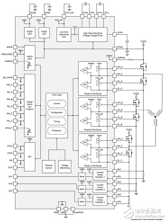
图1.DRV8305-Q1框图
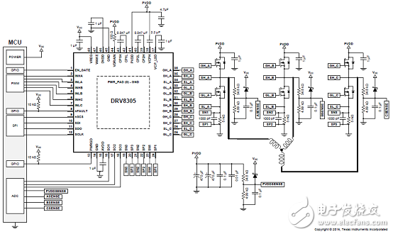
图2.DRV8305-Q1典型应用电路
汽车两轴电动座椅驱动参考设计TIDA-01330
The TIDA-01330 design implements the drive circuitsfor two independent brushed DC motors. It provides asolution for automotive power seats with a highlyintegratedtwo-axis driver, reducing the overall bill ofmaterials. The interface to a simple microcontrollerIllustrates how the design reduces the processingburden on the control software.
In addition to the drive circuit for two motors, this TIDesign also includes current feedback sense circuitsand other diagnostic features to ensure reliableoperation and detection of faults. Additionally thecontrol circuit for an LED illumination element isimplemented, as well as the feasibility of providingtactile feedback to the seat occupant by vibrating ineither axis.
参考设计TIDA-01330主要特性:
• Drives Two Independent Brushed DC Motors
• Up to 10-A Motor Current (Each Axis)
• Current Feedback on Each Axis
• Reverse Battery Protection
• Low-Pass Filtering on Battery Power
• Drives LED for Floor Illumination
• Simple Microcontroller Interface
• Reduced Bill of Materials
参考设计TIDA-01330应用:
• Power Seat Height and Forward and BackwardAdjustment
• Power Seat Back Recline Adjustment andPower Fold
• Other Two-Axis Brushed DC Motor Drives
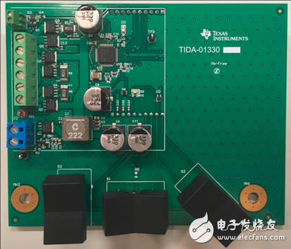
图3.参考设计TIDA-01330外形图
参考设计TIDA-01330主要指标:
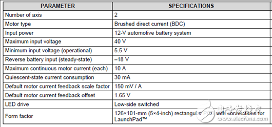
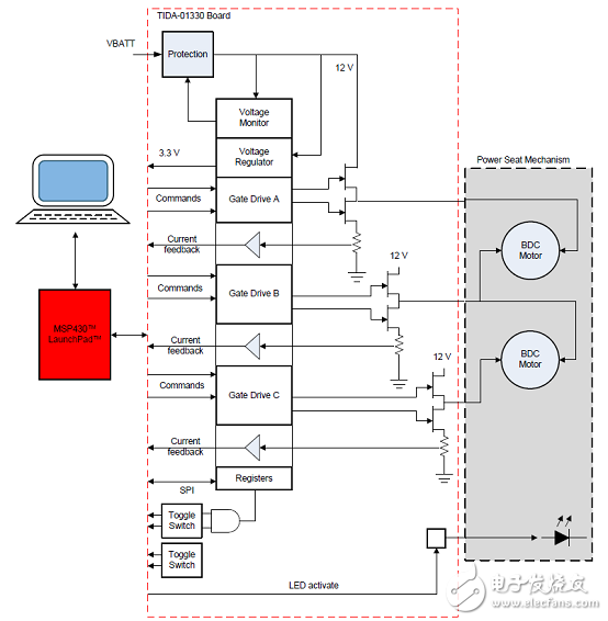
图4.参考设计TIDA-01330框图
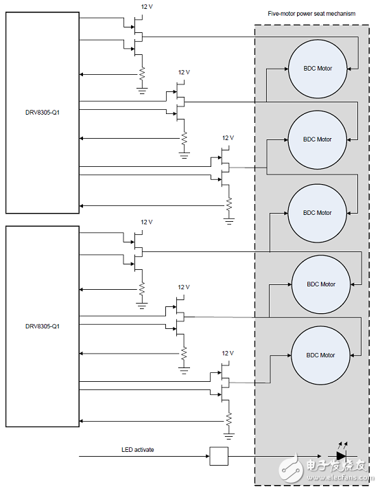
图5.参考设计TIDA-01330扩展到五轴应用图
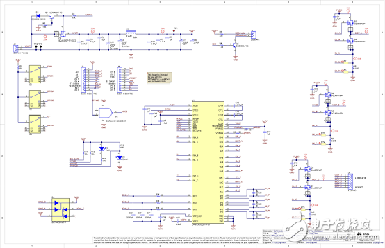
图6.参考设计TIDA-01330电路图
参考设计TIDA-01330材料清单:
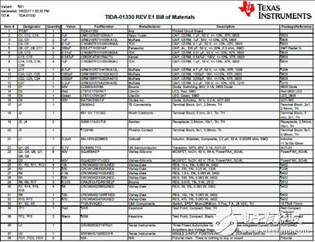
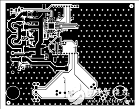
图7.参考设计TIDA-01330 PCB设计图(1)
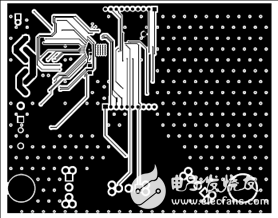
图8.参考设计TIDA-01330 PCB设计图(2)
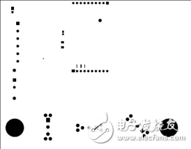
图9.参考设计TIDA-01330 PCB设计图(3)
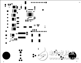
图10.参考设计TIDA-01330 PCB设计图(4)
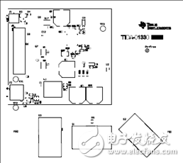
图11.参考设计TIDA-01330 PCB设计图(5)

图12.参考设计TIDA-01330 PCB设计图(6)
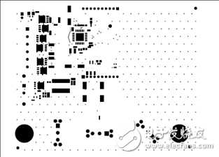
图13.参考设计TIDA-01330 PCB设计图(7)
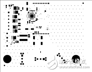
图14.参考设计TIDA-01330 PCB设计图(8)
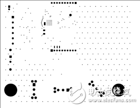
图15.参考设计TIDA-01330 PCB设计图(9)
-
600w的半桥设计图2015-08-05 0
-
自己搭建MOS管桥电路的半桥驱动器2017-01-14 0
-
【转帖】如何实现隔离式半桥栅极驱动器?2018-07-03 0
-
为汽车电动座椅提供解决方案的TIDA-01330技术资料下载2018-07-13 0
-
适用于汽车日行灯的LED驱动器TIDA-01382组装图及物料清单下载2018-07-13 0
-
实现隔离式半桥栅极驱动器的设计途径2018-09-26 0
-
实现隔离式半桥栅极驱动器的设计基础2018-10-16 0
-
实现隔离式半桥栅极驱动器2018-10-23 0
-
LT1160的典型应用:半桥/全桥N沟道功率MOSFET驱动器2019-05-14 0
-
用于工业应用的高压半桥栅极驱动器L63902019-07-08 0
-
请问高效率高精度LED控制驱动电路图怎么设计?2019-09-27 0
-
DRV8313半桥驱动器中文资料2020-07-10 0
-
IR2111半桥驱动器相关资料分享2021-05-19 0
-
CK5G14三相半桥栅极驱动器 CK5G14门极驱动器 普诚授权代理商2022-01-04 0
-
开源硬件-TIDA-01330-汽车 2 轴电动座椅刷式直流电机驱动器 PCB layout 设计2017-12-04 1409
全部0条评论

快来发表一下你的评论吧 !
