

TMS570LS0432主要特性及电动汽车电池管理系统
汽车电子
描述
TI公司的TMS570LS0432/0332是高性能汽车级的16位和32位RISC闪存微控制器,集成了ARM Cortex-R4 CPU,提供1.66 DMIPS/MHz,工作频率高80MHz,性能高达132DMIPS;其安全的架构包括步调一致的两个CPU,CPU和存储器内部自检(BIST)逻辑,闪存和数据SRAM的ECC,外设存储器奇偶校验以及I/O的回送功能,主要用在刷车系统(ABS和ESC),主动辅助驾驶系统,EPS,航空航天,电泵控制,铁路通信,电池管理系统和越野汽车。本文介绍了TMS570LS0432主要特性,功能框图,以及电动汽车电池管理系统(BMS)TIDM-TMS570BMS参考设计主要特性,框图,电路图和材料清单。
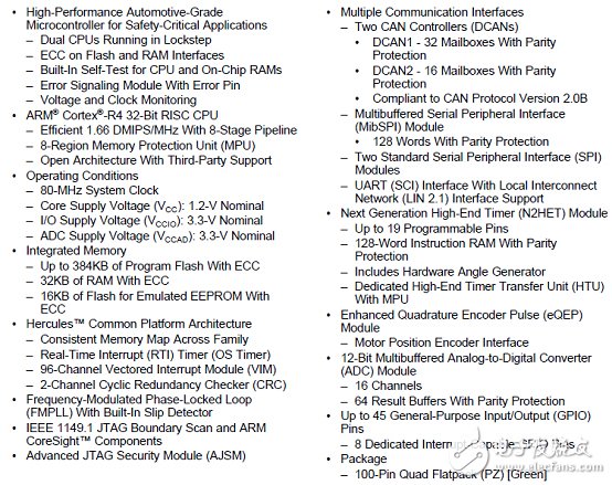
The TMS570LS0432/0332 device is a high-performance automotive-grade microcontroller for safetysystems. The safety architecture includes dual CPUs in lockstep, CPU and Memory BIST logic, ECC onboth the flash and the data SRAM, parity on peripheral memories, and loopback capability on peripheralI/Os.
The TMS570LS0432/0332 device integrates the ARM Cortex-R4 CPU. The CPU offers an efficient1.66 DMIPS/MHz, and has configurations that can run up to 80 MHz, providing up to 132 DMIPS. Thedevice supports the big-endian (BE32) format.
The TMS570LS0432/0332 device has 384KB and 256KB of integrated flash (respectively) and 32KB ofdata RAM. Both the flash and RAM have single-bit error correction and double-bit error detection. Theflash memory on this device is a nonvolatile, electrically erasable, and programmable memoryimplemented with a 64-bit-wide data bus interface. The flash operates on a 3.3-V supply input (the samelevel as I/O supply) for all read, program, and erase operations. When in pipeline mode, the flash operateswith a system clock frequency of 80 MHz. The SRAM supports single-cycle read and write accesses in byte, halfword, word, and double-word modes throughout the supported frequency range.
The TMS570LS0432/0332 device features peripherals for real-time control-based applications, including aNext Generation High-End Timer (N2HET) timing coprocessor with up to 19 I/O terminals and a 12-bitAnalog-to-Digital Converter (ADC) supporting 16 inputs in the 100-pin package.
The N2HET is an advanced intelligent timer that provides sophisticated timing functions for real-timeapplications. The timer is software-controlled, using a small instruction set, with a specialized timermicromachine and an attached I/O port. The N2HET can be used for pulse-width-modulated outputs,capture or compare inputs, or GPIO. The N2HET is especially well suited for applications requiringmultiple sensor information and drive actuators with complex and accurate time pulses. A High-End TimerTransfer Unit (HTU) can perform DMA-type transactions to transfer N2HET data to or from main memory.A Memory Protection Unit (MPU) is built into the HTU.
The Enhanced Quadrature Encoder Pulse (eQEP) module is used for direct interface with a linear orrotary incremental encoder to get position, direction, and speed information from a rotating machine asused in high-performance motion and position-control systems.
The device has a 12-bit-resolution MibADC with 16 channels and 64 words of parity-protected buffer RAM.The MibADC channels can be converted individually or can be grouped by software for sequentialconversion sequences. There are three separate groupings. Each sequence can be converted once whentriggered or configured for continuous conversion mode. The MibADC has a 10-bit mode for use whencompatibility with older devices or faster conversion time is desired.
The device has multiple communication interfaces: one MibSPI, two SPIs, one UART/LIN, and twoDCANs. The SPI provides a convenient method of serial high-speed communications between similarshift-register type devices. The UART/LIN supports the Local Interconnect standard 2.1 and can be usedas a UART in full-duplex mode using the standard Non-Return-to-Zero (NRZ) format. The DCAN supportsthe CAN 2.0 (A and B) protocol standard and uses a serial,multimaster communication protocol thatefficiently supports distributed real-time control with robust communication rates of up to 1 Mbps. TheDCAN is ideal for applications operating in noisy and harsh environments (for example,automotive andindustrial applications) that require reliable serial communication or multiplexed wiring.
The Frequency-Modulated Phase-Locked Loop (FMPLL) clock module is used to multiply the externalfrequency reference to a higher frequency for internal use. The FMPLL provides one of the five possibleclock source inputs to the Global Clock Module (GCM)。 The GCM manages the mapping between theavailable clock sources and the device clock domains.
The device also has an External Clock Prescaler (ECP) module that when enabled, outputs a continuousexternal clock on the ECLK pin. The ECLK frequency is a user-programmable ratio of the peripheralinterface clock (VCLK) frequency.This low-frequency output can be monitored externally as an indicator ofthe device operating frequency.
The Error Signaling Module(ESM) monitors all device errors and determines whether an interrupt is generated or the external nERROR pin is toggled when a fault is detected. The nERROR pin can bemonitored externally as an indicator of a fault condition in the microcontroller.The I/O Multiplexing and Control Module (IOMM) allows the configuration of the input/output pins tosupport alternate functions.
With integrated safety features and a wide choice of communication and control peripherals, theTMS570LS0432/0332 device is an ideal solution for real-time control applications with safety-criticalrequirements.
TMS570LS0432主要特性:
TMS570LS0432主要应用:
• Braking Systems (ABS and ESC)
• Active Driver Assistance Systems
• Electric Power Steering (EPS)
• Aerospace and Avionics
• Electric Pump Control
• Railway Communications
• Battery-Management Systems
• Off-road Vehicles
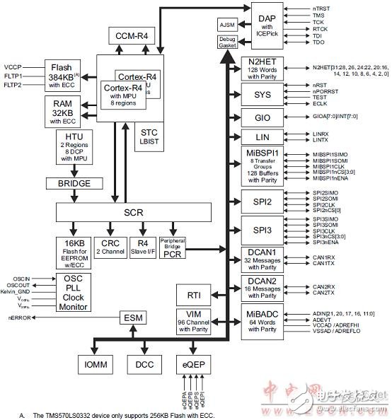
图1.TMS570LS0432功能框图
电动汽车电池管理系统(BMS)TIDM-TMS570BMS参考设计
TMS570 Active Cell-Balancing Battery-Management Design Guide
This battery-management system (BMS) example illustrates a TMS570LS0432 (an ISO 26262 capable)MCU supporting active cell balancing between one cell in a 16-cell battery module and a 12-V supply.Self-diagnostic functions are enabled to monitor the status of TMS570LS0432 during run time.TMS570LS0432 configures BQ76PL455A-Q1 to monitor battery cell status through a UART port.
TMS570LS0432 analyzes the cell data and generates a balancing command. The real-time interrupt (RTI)timer is configured to schedule active balancing functions. The balancing command is passed through theserial peripheral interface (SPI) to EMB1428Q and EMB1499Q to enable charge or discharge of the cellselected. The user can view the cell voltage and other status data and control the system operation usinga graphical user interface (GUI) running on the host PC. TMS570LS0432 communicates with the host PC through a UART port emulated by the N2HET module.
The software accompanying this design is developed and tested on a TMS570LS0432 LaunchPad™(LAUNCHXL-TMS57004) and an EM1402 EVM.
Plug-in Hybrid Electric Vehicles (PHEV) and Battery Electric Vehicles (BEV) are two quickly emerging technologies which use powerful electric motors as the propulsion source. In order to power these electric motors, large battery packs made up of hundreds of cells totaling 300-400 volts are installed in the vehicle. Since batteries have a finite energy capacity, PHEV and BEV must be recharged on a periodic basis, typically by connecting to the power grid.
The charging system for these vehicles consists of a an AC/DC rectifier to generate a DC voltage from the AC line followed by a DC/DC converter to generate the DC voltage required by the battery pack. Additionally, advanced charging systems might also communicate with the power grid using PLC modems to adjust charging based on power grid conditions. The battery pack must also be carefully monitored during operation and the charging process in order to maximize energy usage and prolong battery life.High-performance analog parts are also available to provide critical system functions and features such as sensor feedback, isolation, chip power supplies, and communication transceivers.
The bq7xPLxxx device families are designed for high cell count battery packs. They can handle the voltages and currents found in higher power applications like power tools and electronic mobility. The more cells a pack has in series, the greater the difference in state of charge, impedance and capacitance affect the health and energy deliver of the pack. The bq7xPLxxx devices include circuitry for bringing the cells back into balance. This increases lifetime of the pack and can help deliver as much energy to the application as possible. Each bq7xPLxxx device protects from over charge, over discharge, over temperature and high current events for pack and system safety.
A system example for an active cell balancing battery management system. The TMS570LS0432 microcontroller commands EMB1402 EVM to monitor the battery cells and perform charge/discharge from one battery cell to an external 12V supply. The user can view the cell status and control cell balancing from a GUI running on the host PC.
电池管理系统(BMS)参考设计TIDM-TMS570BMS主要特性:
设计特性:
• The Diagnostic Features of TMS570LS0432microcontroller (MCU) Are Enabled to Monitor andReport TMS570LS0432 Status During Run Time.
• The TMS570LS0432 MCU ConfiguresBQ76PL455A-Q1 for Monitoring Cell Voltages andChecking BQ76PL455A-Q1 Status During RunTime.
• The TMS570LS0432 MCU Analyzes the Data FromAll Cells and Generates Active Cell BalancingCommands.
• The TMS570LS0432 MCU Commands EMB1428Qfor Cell Balancing and Monitors EMB1428Q andEMB1499Q Status During Run Time.
• The TMS570LS0432 MCU Communicates WithHost PC Through a Universal AsynchronousReceiver and Transmitter (UART) Emulated by theNext Generation High-End Timer (N2HET) Moduleto Display the Status and Control the BalancingOperation During Run Time.
主要应用:
• Electric and Hybrid Electric Vehicles (EVs, HEVs,PHEVs, and mild hybrids)
• Energy Storage Systems (ESS)
• Uninterruptible Power Supplies (UPSs)
• E-Bikes and E-Scooters
图2.电池管理系统(BMS)参考设计TIDM-TMS570BMS外形图
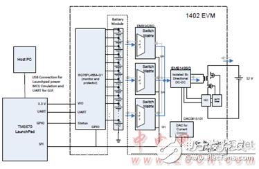
图3.参考设计TIDM-TMS570BMS框图(1)
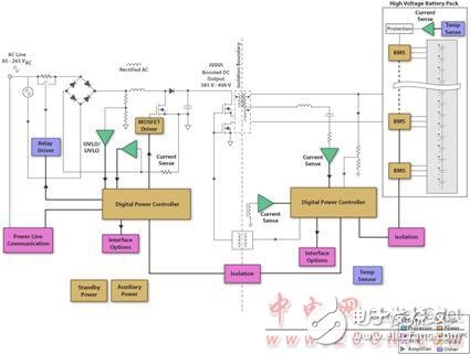
图4.参考设计TIDM-TMS570BMS框图(2)
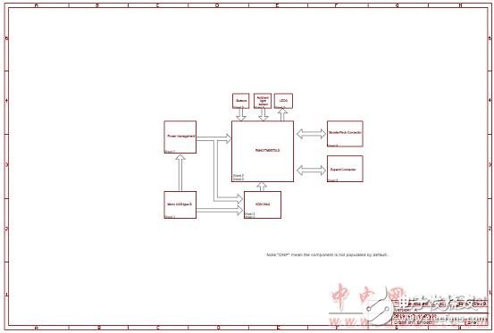
图5.参考设计TIDM-TMS570BMSLaunchPad电路图(1)
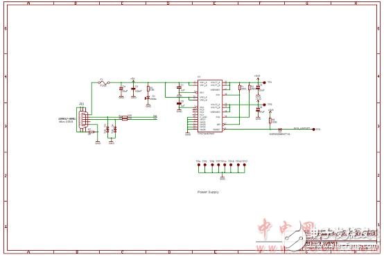
图6.参考设计TIDM-TMS570BMSLaunchPad电路图(2)
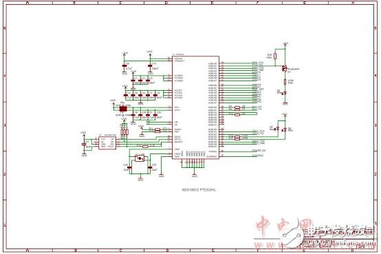
图7.参考设计TIDM-TMS570BMSLaunchPad电路图(3)
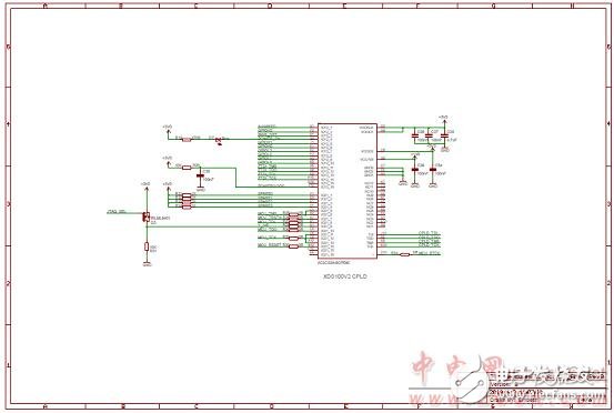
图8.参考设计TIDM-TMS570BMSLaunchPad电路图(4)
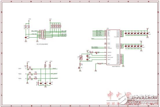
图9.参考设计TIDM-TMS570BMSLaunchPad电路图(5)
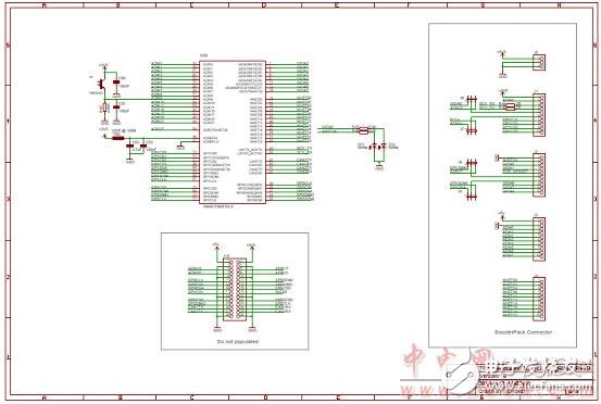
图10.参考设计TIDM-TMS570BMSLaunchPad电路图(6)
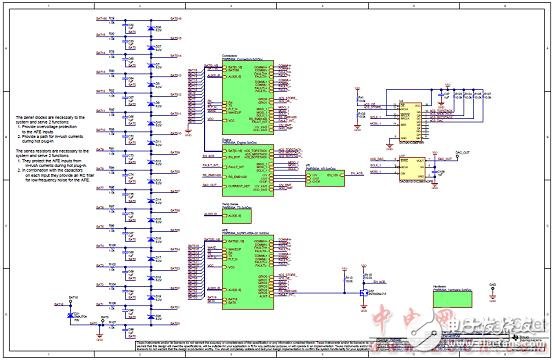
图11.参考设计TIDM-TMS570BMSEM1402 EVM电路图(1)
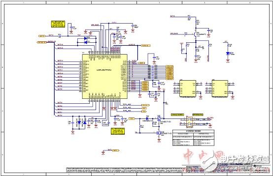
图12.参考设计TIDM-TMS570BMSEM1402 EVM电路图(2)
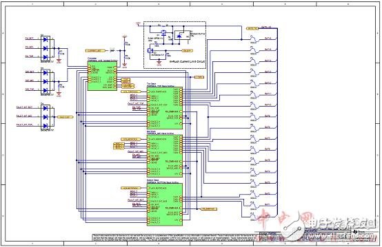
图13.参考设计TIDM-TMS570BMSEM1402 EVM电路图(3)
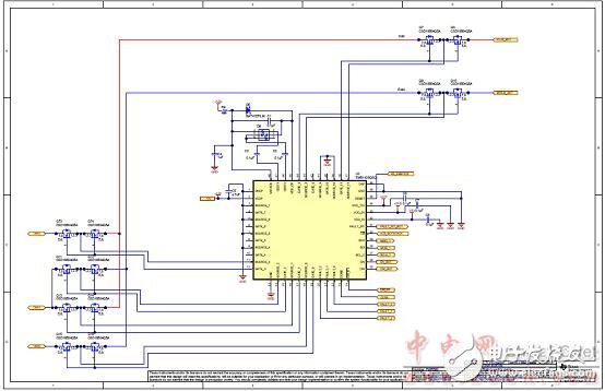
图14.参考设计TIDM-TMS570BMSEM1402 EVM电路图(4)
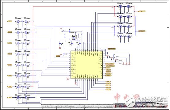
图15.参考设计TIDM-TMS570BMSEM1402 EVM电路图(5)

图16.参考设计TIDM-TMS570BMSEM1402 EVM电路图(6)
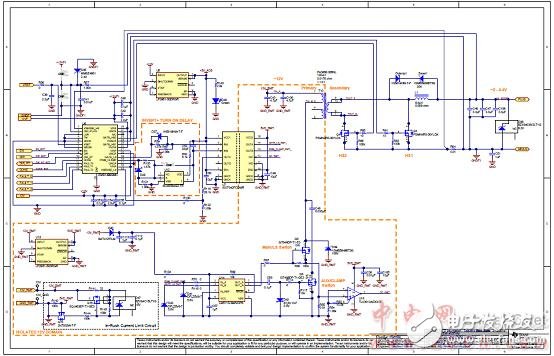
图17.参考设计TIDM-TMS570BMSEM1402 EVM电路图(7)
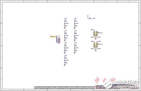
图18.参考设计TIDM-TMS570BMSEM1402 EVM电路图(8)
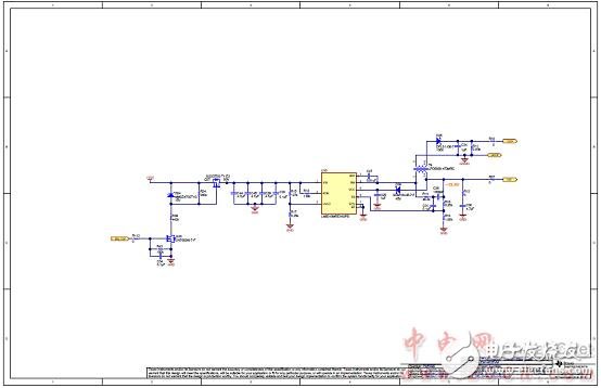
图19.参考设计TIDM-TMS570BMSEM1402 EVM电路图(9)
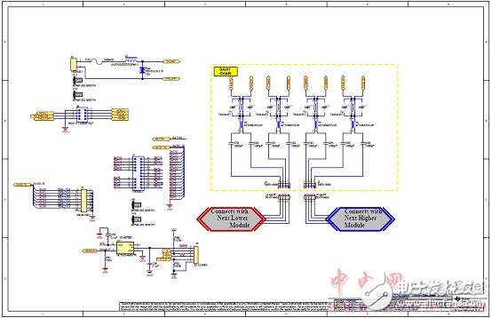
图20.参考设计TIDM-TMS570BMSEM1402 EVM电路图(10)
LaunchPad™(LAUNCHXL-TMS57004) and an EM1402 EVM
TMS570LS0432 Launchpad材料清单(BOM):
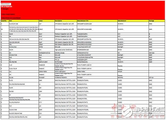
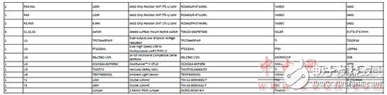
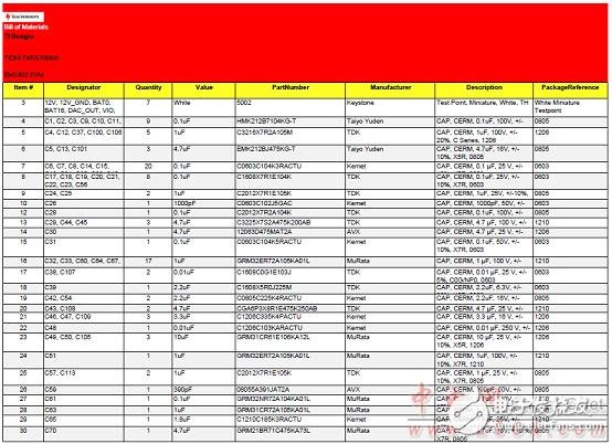
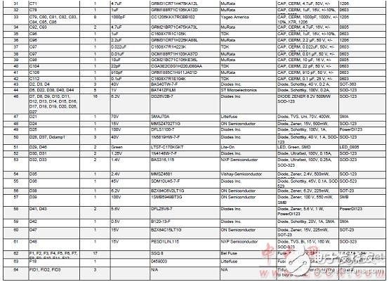
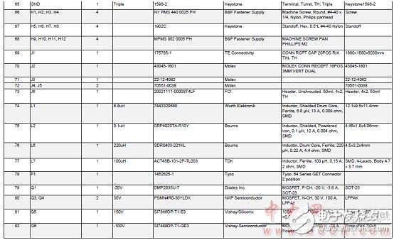
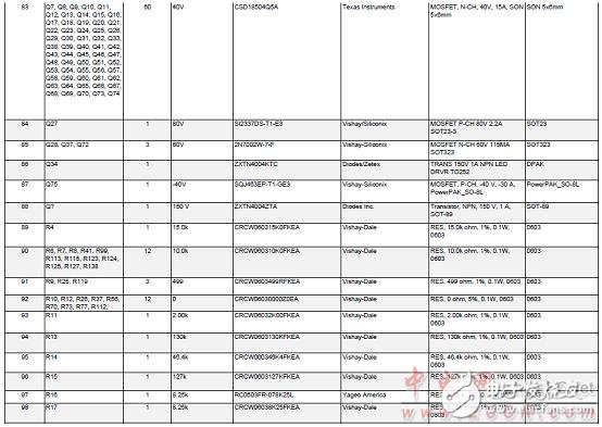
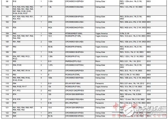
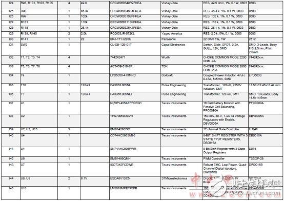
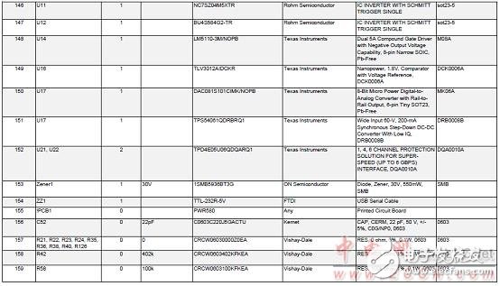
EM1402 EVM材料清单(BOM):
- 相关推荐
- ti
- 闪存微控制器
- tms570ls0432
-
电动汽车电池管理系统AD采样的设计2011-03-23 0
-
【EVB-335X-II申请】电动汽车电池管理系统开发2015-10-21 0
-
【UT4418申请】电动汽车电池管理系统(BMS)开发2015-10-27 0
-
【GoKit申请】电动汽车电池管理系统开发2015-11-02 0
-
请问TMS570_714和TMS570_432能否实现CAN在线软件升级?2018-05-22 0
-
请问tms570ls0432与bq76pl455怎么连接?2018-05-25 0
-
TMS570LS0432的SCI串口通信只能发送不能接收数据是什么原因?2018-05-25 0
-
TMS570ls0432 用HET配置PWM问题2018-06-23 0
-
请问哪里可以看到TMS570LS0432的例程?2018-08-08 0
-
有源电池平衡电池管理系统高性能MCU包括BOM及层图2018-10-17 0
-
TMS570LS0432 launchpad串口中断进不去2021-04-08 0
-
电动汽车热管理系统和性能2021-04-23 0
-
怎么实现电动汽车电池管理系统设计?2021-05-19 0
-
tms570ls0432/0332 16/32位RISC单片机闪存微控制器英文原版资料2018-04-17 990
-
TMS570有源电池平衡电池管理设计指南详细说明2020-08-17 641
全部0条评论

快来发表一下你的评论吧 !
