

ADI AD7280A1主要特性及15通道锂电池管理模块BMU基本功能
汽车电子
描述
ADI公司的15通道锂电池管理模块主要采用AD7280A,AD8280,ADuM5401,ADuM1201, ADuC7026和AD8601,实现了对15个锂电池单体的电压和温度监测,在保证信号监测精度的同时,提供了主监测电路和次级监测电路的架构,实现更高级别的系统保护。还提供了模块化可扩展的板级架构,除主监测电路模块,次级监测电路模块,数据接口模块外,可扩展主动均衡电路等其他模块,方便系统原型开发。本文介绍了AD7280A1主要特性,框图和应用电路,以及15通道锂电池管理模块BMU基本功能,框图,电路图,材料清单和PCB元件布局图和设计图。
The AD7280A1 contains all the functions required for general- purpose monitoring of stacked lithium ion batteries as used in hybrid electric vehicles, battery backup applications, and power tools. The part has multiplexed cell voltage and auxiliary ADC measurement channels for up to six cells of battery management. An internal ±3 ppm/°C reference is provided that allows a cell voltage accuracy of ±1.6 mV. The ADC resolution is 12 bits and allows conversion of up to 48 cells within 7 μs. The AD7280A operates from a single VDD supply that has a range of 8 V to 30 V (with an absolute maximum rating of 33 V)。 The part provides six differential analog input channels to accommodate large common-mode signals across the full VDD range. Each channel allows an input signal range, VIN(+) − VIN(−), of 1 V to 5 V. The input pins assume a series stack of six cells. In addition, the part includes six auxiliary ADC input channels that can be used for temperature measurement or system diagnostics.
The AD7280A includes on-chip registers that allow a sequence of channel measurements to be programmed to suit the application requirements. The AD7280A also includes a dynamic alert function that can detect whether the cell voltages or auxiliary ADC inputs exceed an upper or lower limit defined by the user. The AD7280A has cell balancing interface outputs designed to control external FET transistors to allow discharging of individual cells. The AD7280A includes a built-in self-test feature that internally applies a known voltage to the ADC inputs. A daisy-chain interface allows up to eight parts to be stacked without the need for individual device isolation. The AD7280A requires only one supply pin that accepts 6.9 mA under normal operation while converting at 1 MSPS. All this functionality is provided in a 48-lead LQFP package operating over a temperature range of −40°C to +105°C.
AD7280A1主要特性:
12-bit ADC, 1 μs per channel conversion time
6 analog input channels, common-mode range 0.5 V to 27.5 V
6 auxiliary ADC inputs
±1.6 mV cell voltage accuracy
On-chip voltage regulator
Cell balancing interface
Daisy-chain interface
Internal reference: ±3 ppm/oC
1.8 μA power-down current
High input impedance
Serial interface with alert function
1 SPI interface for up to 48 channels
CRC protection on read and write commands
On-chip registers for channel sequencing
VDD operating range: 8 V to 30 V
Temperature range: −40℃ to +105℃
48-lead LQFP Qualified for automotive applications
AD7280A1应用:
Lithium ion battery monitoring
Electric and hybrid electric vehicles
Power supply backup
Power tools
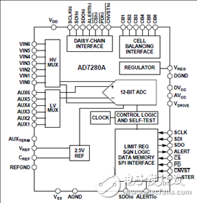
图1.AD7280A1功能框图
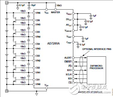
图2.AD7280A1六电池配置图
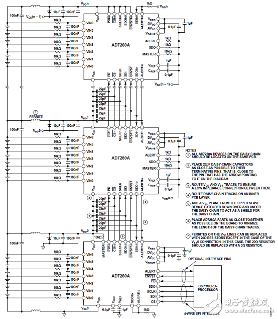
图3.AD7280A1菊花链配置图
15通道锂电池管理模块BMU
The 15ch BMU demo board is a tool for user to evaluate ADI Li-ion BMS chipset, including primary cellmonitoring IC AD7280A, backup cell monitoring IC AD8280, digital isolator ADuM1201, power isolatorADuM5401/03,and MCU ADuC7026. User can connect the board to Li-ion cells, connect with CAN tooltool set orPC directly, to enable in-system evaluation. This document describes basic operation of the 15ch BMU DEMO.
15通道锂电池管理模块BMU基本功能:
- Primary cell monitoring
o Up to 15 cell voltage inputs
o Up to 18temperature inputs
o 12-bit resolution of conversion data
o Alert of Over-Voltage, Under-Voltage, Over-Temperature, and Under-Temperature
o Self-Test
o Configurable acquisition time, conversion channels, averaging.
- Backup cell monitoring
o Up to 15 cell voltage inputs
o Up to 6 temperature inputs
o Alert outputs of Over-Voltage, Under-Voltage, and Over-Temperature
o Self-Test
- Passive cell balancing
o 100mA peak current
- 14V power supply with power enable input
- 1x CAN interface
- 1x USB interface
For GUI evaluation, user can connect the demo boardsto:
a. PC directly through USB cable. PC runs ‘15ch BMU Demo GUI (USB Version)’。
b. ZLG CANalyst (USBCAN-I or USBCAN-II) through CAN bus, then to PC. PC runs ‘15ch BMU Demo GUI (CANVersion)’。
c. Other types ofCAN tool through CAN bus, then to PC. PC runs specific GUI or analyzer tool according tothe CAN tool.
15通道锂电池管理模块BMU包括:
- Primary Monitoring Board
- Backup Monitoring Board
- Data Interface Board
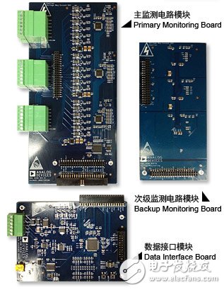
图4.15通道锂电池管理模块BMU外形图
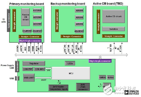
图5.15通道锂电池管理模块BMU框图
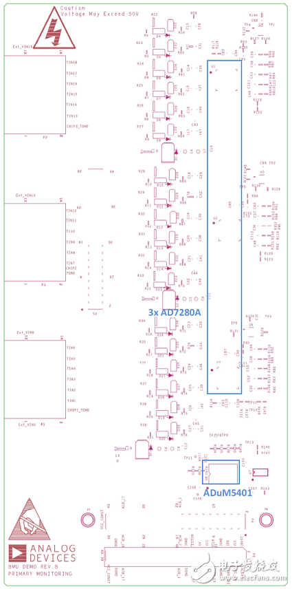
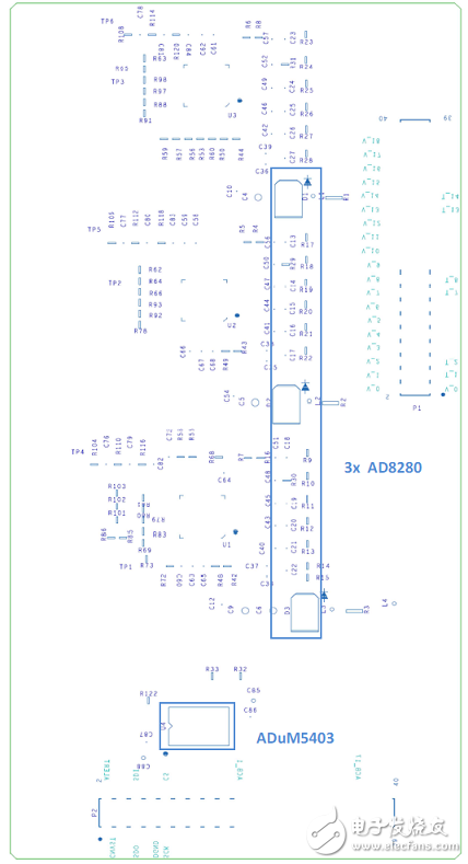
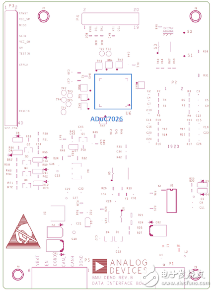
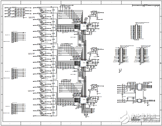
图6.15通道锂电池管理模块BMU监视板电路图
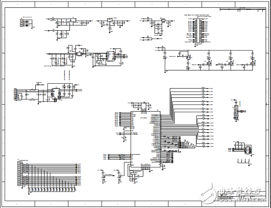
图7.15通道锂电池管理模块BMU数据板电路图
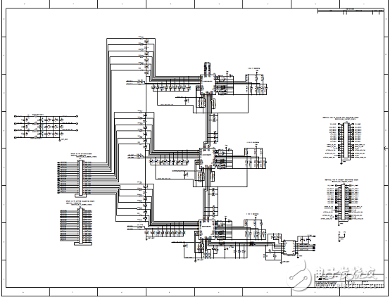
图8.15通道锂电池管理模块BMU备份监视板电路图
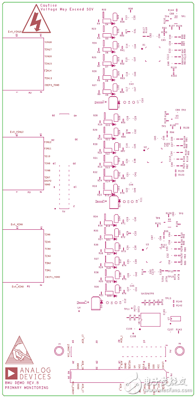
图9.15通道锂电池管理模块BMU监视板PCB顶层元件布局图
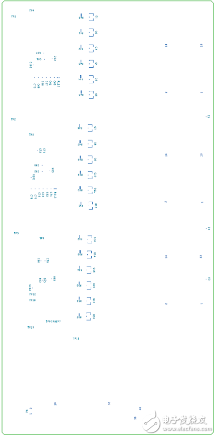
图10.15通道锂电池管理模块BMU监视板PCB底层元件布局图
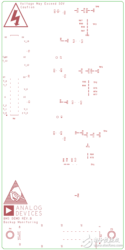
图11.15通道锂电池管理模块BMU备份监视板PCB顶层元件布局图
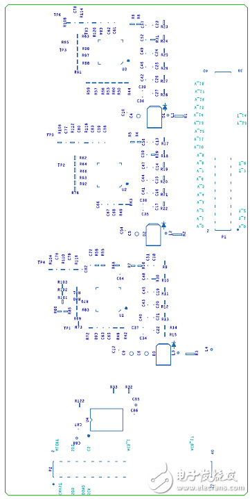
图12.15通道锂电池管理模块BMU备份监视板PCB底层元件布局图
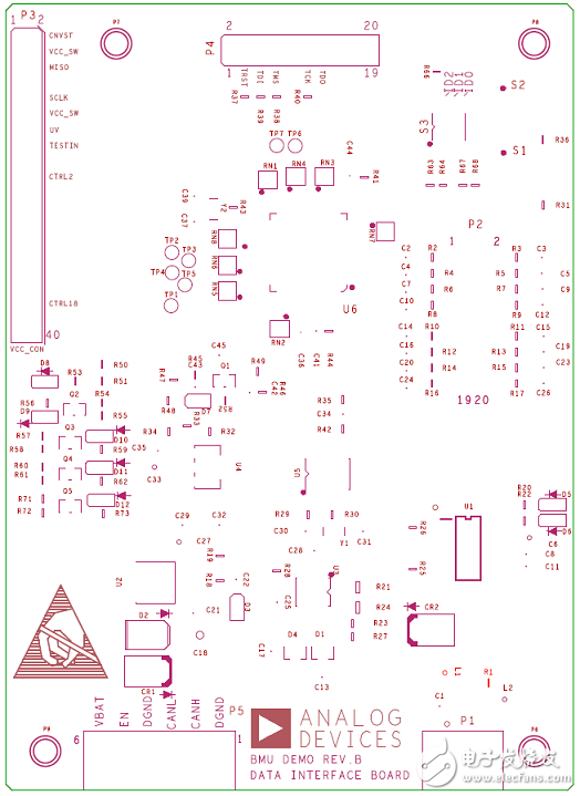
图13.15通道锂电池管理模块BMU数据板PCB顶层元件布局图
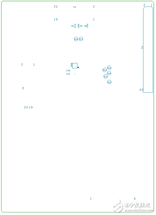
图14.15通道锂电池管理模块BMU数据板PCB底层元件布局图
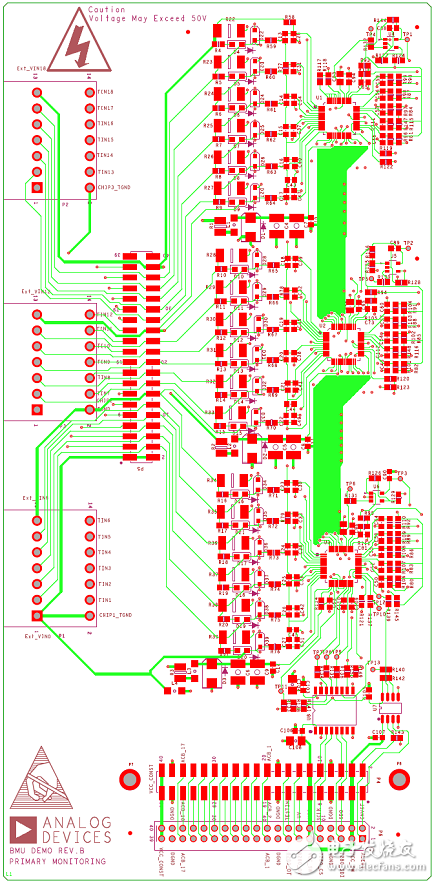
图15.15通道锂电池管理模块BMU监视板PCB设计图(1)
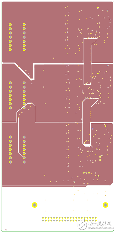
图16.15通道锂电池管理模块BMU监视板PCB设计图(2)
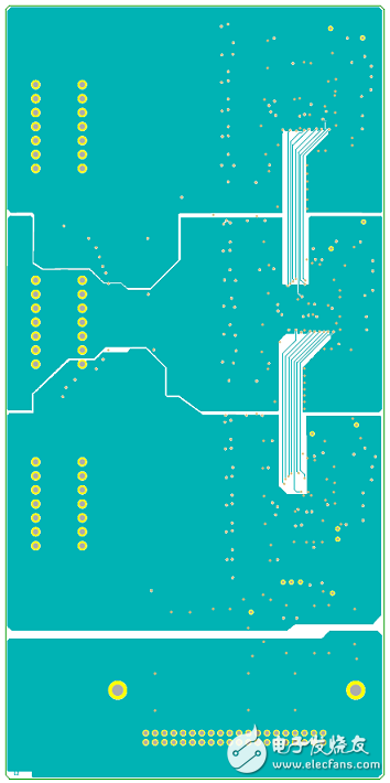
图17.15通道锂电池管理模块BMU监视板PCB设计图(3)
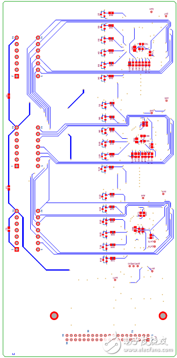
图18.15通道锂电池管理模块BMU监视板PCB设计图(4)
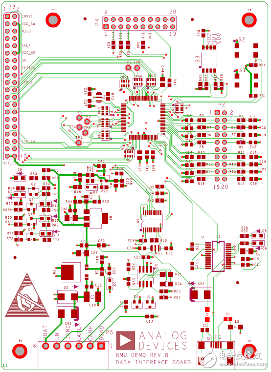
图19.15通道锂电池管理模块BMU数据板PCB设计图(1)
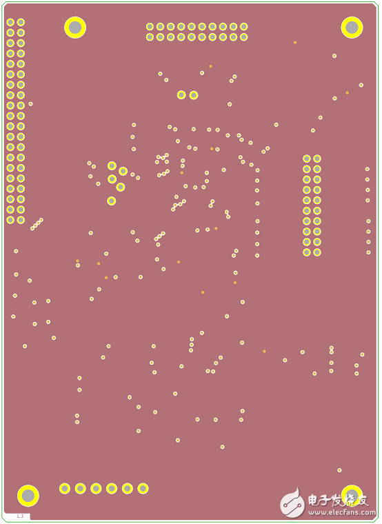
图20.15通道锂电池管理模块BMU数据板PCB设计图(2)
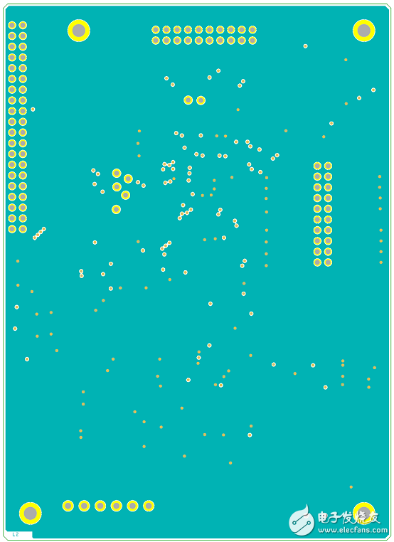
图21.15通道锂电池管理模块BMU数据板PCB设计图(3)
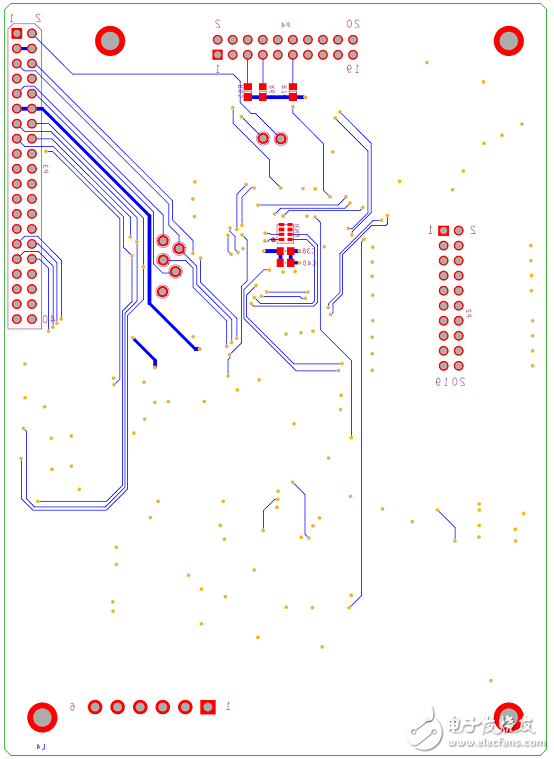
图22.15通道锂电池管理模块BMU数据板PCB设计图(4)
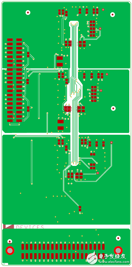
图23.15通道锂电池管理模块BMU备份监视板PCB设计图(1)
图24.15通道锂电池管理模块BMU备份监视板PCB设计图(2)
-
关于锂电池管理系统设计2012-02-23 0
-
5A双节锂电池充电管理集成电路CN30022013-05-23 0
-
磷酸铁锂电池的特性解析与电源管理芯片的应用2015-10-13 0
-
锂电池应用方法及保护措施2016-01-07 0
-
5A 双节锂电池充电管理集成电路 CN30022016-04-12 0
-
ADI解决方案助力锂电池测试设备设计2018-08-23 0
-
ADI锂电池测试设备方案2018-09-26 0
-
1A 线性锂电池充电管理芯片 ZCC40562020-02-25 0
-
多串锂电池充电管理--之筋膜枪2020-04-18 0
-
三节锂电池充电管理芯片 IC电路图如何设计2020-12-12 0
-
三节锂电池充电管理芯片电路图2021-01-28 0
-
2A锂电池充电管理芯片2021-02-23 0
-
5A四节锂电池充电管理CN3704相关资料下载2021-03-26 0
-
SM5102 是一款锂电池充放电管理专用芯片.2023-11-06 0
-
AD7280A锂电池监控器用于电动/混合动力汽车以及能量存储2019-07-30 3122
全部0条评论

快来发表一下你的评论吧 !
