

ST公司的STM8AF5286主要特性及框图
汽车电子
描述
ST公司的STM8AF5286是用于汽车的8位MCU,配置了多达128KB闪存,数据EEPROM,10位ADC,计时器,LIN,CAN,USART,SPI,I2C等接口,工作电压3-5.5V, STM8 CPU内核采用哈佛架构和三级流水线,工作频率高达24MHz,采用STM8A-DISCOVERY套件评估.本文介绍了STM8AF5286主要特性,框图,以及STM8A-DISCOVERY Discovery开发板主要特性,STM8AF板和STM8AL板硬件框图,电路图和材料清单.
The STM8AF526x/8x/Ax and STM8AF6269/8x/Ax automotive 8-bit microcontrollers described in this datasheet offer from 32 Kbyte to 128 Kbyte of non volatile memory and integrated true data EEPROM. They are referred to as high density STM8A devices in STM8S series and STM8AF series 8-bit microcontrollers reference manual (RM0016).The STM8AF52 series features a CAN interface.
All devices of the STM8A product line provide the following benefits: reduced system cost, performance and robustness, short development cycles, and product longevity.
The system cost is reduced thanks to an integrated true data EEPROM for up to 300 k write/erase cycles and a high system integration level with internal clock oscillators, wtachdog, and brown-out reset.
Device performance is ensured by 20 MIPS at 24 MHz CPU clock frequency and enhanced characteristics which include robust I/O, independent watchdogs (with a separate clock source), and a clock security system.
Short development cycles are guaranteed due to application scalability across a common family product architecture with compatible pinout, memory map, and modular peripherals. Full documentation is offered with a wide choice of development tools.
Product longevity is ensured in the STM8A family thanks to their advanced core which is made in a state-of-the art technology for automotive applications with 3.3 V to 5.5 V operating supply.
All STM8A and ST7 microcontrollers are supported by the same tools including STVD/STVP development environment, the STice emulator and a low-cost, third party in-circuit debugging tool.
STM8AF5286主要特性:
Core
– Max fCPU: 24 MHz
– Advanced STM8A core with Harvard architecture and 3-stage pipeline
– Average 1.6 cycles/instruction resulting in 10 MIPS at 16 MHz fCPU for industry standard benchmark
Memories
– Program memory: 32 to 128 Kbyte Flash program; data retention 20 years at 55 ℃
– Data memory: up to 2 Kbyte true data EEPROM; endurance 300 kcycle
– RAM: 6 Kbyte
Clock management
– Low-power crystal resonator oscillator with external clock input
– Internal, user-trimmable 16 MHz RC and low-power 128 kHz RC oscillators
– Clock security system with clock monitor
Reset and supply management
– Wait/auto-wakeup/Halt low-power modes with user definable clock gating
– Low consumption power-on and power-down reset
Interrupt management
– Nested interrupt controller with 32 vectors
– Up to 37 external interrupts on 5 vectors
Timers
– 2 general purpose 16-bit timers with up to 3 CAPCOM channels each(IC, OC, PWM)
– Advanced control timer: 16-bit, 4 CAPCOM channels, 3 complementary outputs, dead-time insertion and flexible synchronization
– 8-bit AR basic timer with 8-bit prescaler
– Auto-wakeup timer
– Window and independent watchdog timers
I/Os
– Up to 68 user pins (11 high sink I/Os)
– Highly robust I/O design, immune against current injection
Communication interfaces
– High speed 1 Mbit/s CAN 2.0B interface
– USART with clock output for synchronous operation - LIN master mode
– LINUART LIN 2.2 compliant, master/slave modes with automatic resynchronization
– SPI interface up to 10 Mbit/s or fMASTER/2
– I2C interface up to 400 Kbit/s
Analog to digital converter (ADC)
– 10-bit resolution, 2 LSB TUE, 1 LSB linearity and up to 16 multiplexed channels
Operating temperature up to 150 ℃
Qualification conforms to AEC-Q100 grade 0
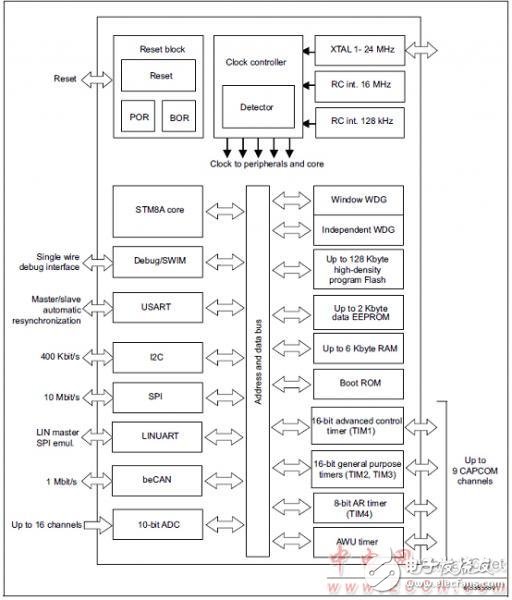
图1.STM8AF526x/8x/Ax和STM8AF6269/8x/Ax框图
STM8A-DISCOVERY Discovery开发板
The STM8A-DISCOVERY helps you discover the STM8AF and STM8AL automotive
microcontroller family features and develop your applications through two dedicated application boards that can be connected together via a LIN network.
The STM8AF board can perform both CAN and LIN communications with the MCU poweredat 5 V and is ready to be connected into a network with its integrated transceiver.
The STM8AL board manages LIN slave communication through its transceiver and uses a 4-digit alphanumeric LCD display with the MCU powered at 3.3 V, offering low energy powermodes.
Both STM8AF and STM8AL boards include push buttons, LEDs, external connectors and allow various configurations to take advantage of the numerous capabilities of themicrocontrollers.
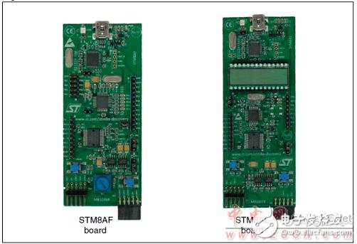
图2.STM8A-DISCOVERY Discovery开发板外形图
STM8AF和STM8AL板共同特性:
● On-board ST-LINK/V2 included for debugging and programming
● Board power supply: through 5 V USB bus
● Internal dual ST662A step-up converter building the 12 Vdc when powered by USBport
● External application power supply VBAT (up to 14 Vdc)
● 16 MHz HSE XTAL crystal oscillator
● L99PM62GXP power management IC with LIN and high speed CAN with SPI control
interface and high-side drivers
● Two push buttons (USER1 and USER2)
● Extension header for L99PM62GXP including relays, high-side outputs and wake-up
Capabilities
STM8AF板特有特性:
● STM8AF5288T microcontroller featuring 64 Kbytes Flash, 2 Kbytes data EEPROM,
LIN, CAN in an 48-pin package
● Seven LEDs:
– LD1 (red/green) for USB communication
– LD2 (red) for 5 V power ON
– Five user LEDs LD3 (red) and LD4 to LD7 (green)
● RV1 potentiometer connected to the ADC peripheral
● Extension headers for MCU connectivity (full Port B, free ports pins, RESET)
STM8AL板特有特性:
● STM8AL3L68T microcontroller featuring 32 Kbytes Flash, 1 Kbytes data EEPROM,
LCD in an 48-pin package
● Four LEDs:
– LD1 (red/green) for USB communication
– LD2 (red) for 3.3 V power ON
– 2 user LEDs LD3 (red) and LD4 (green)
● 4-digit alphanumeric LCD display including 4 bars display
● Extension header for MCU connectivity (free ports pins, RESET)
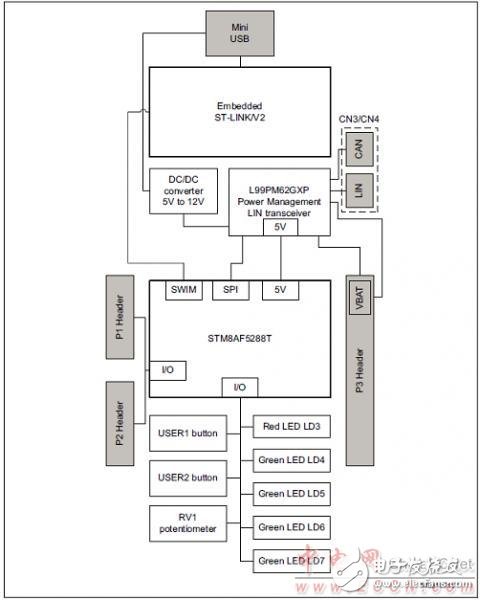
图3.STM8AF板硬件框图
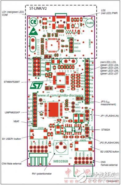
图4.STM8AF板正面布局图
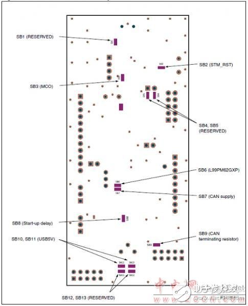
图5.STM8AF板背面布局图
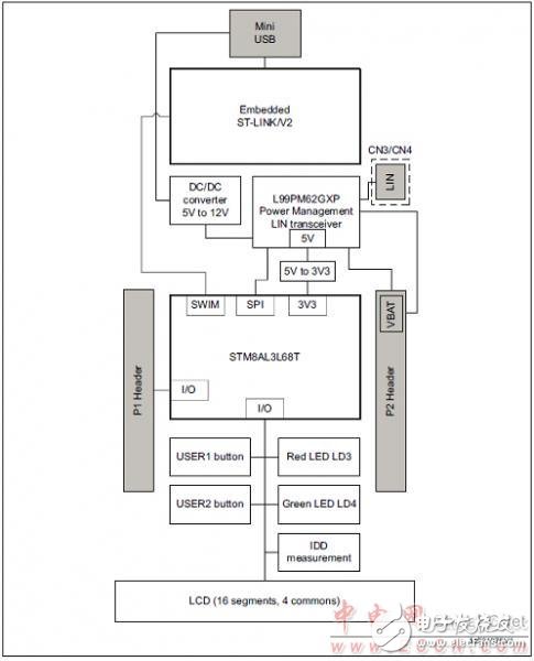
图6.STM8AL板硬件框图
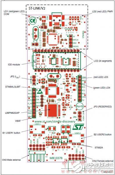
图7.STM8AL板正面布局图
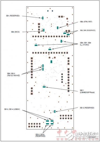
图8.STM8AL板背面布局图
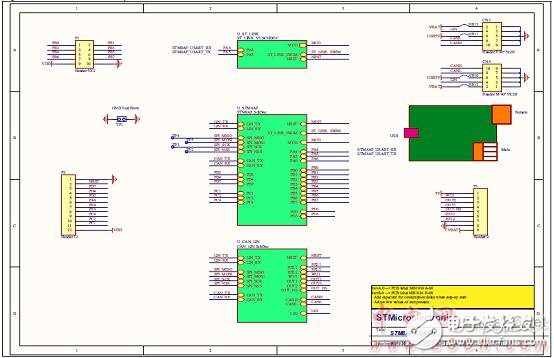
图9.STM8AF板电路图(1)
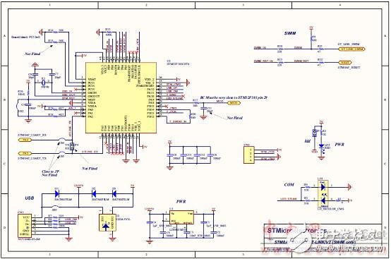
图10.STM8AF板电路图(2):ST-LINK/V2 (仅仅SWIM)
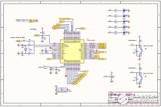
图11.STM8AF板电路图(3):MCU
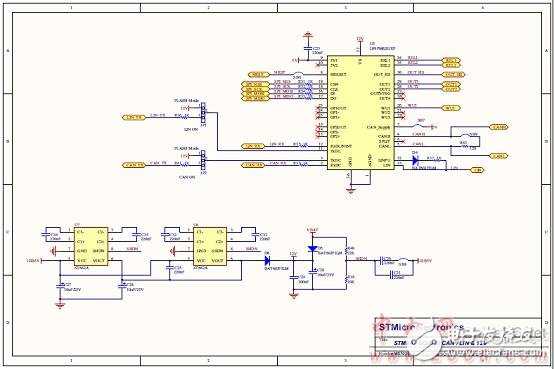
图12.STM8AF板电路图(4):CAN/LIN和12V
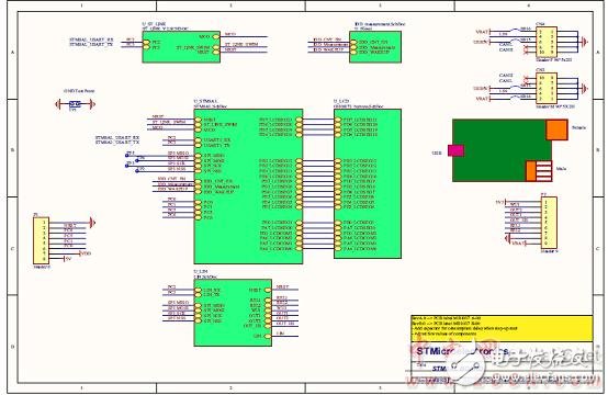
图12.STM8AL板电路图(1)
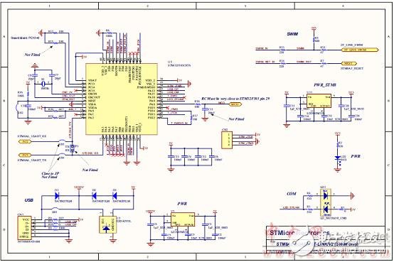
图13.STM8AL板电路图(2):ST-LINK/V2 (仅仅SWIM)
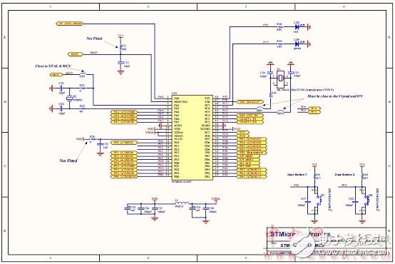
图14.STM8AL板电路图(3):MCU
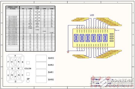
图15.STM8AL板电路图(4):LCD
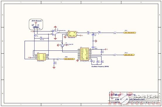
图16.STM8AL板电路图(5):IDD测量
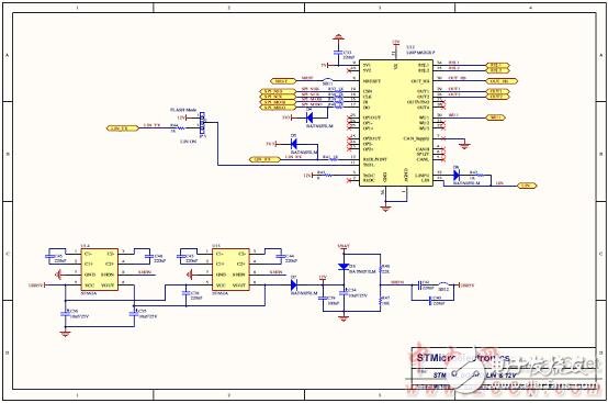
图17.STM8AL板电路图(5):LIN和12V
-
无法使用MCU名称STM8AF5289设置配置2019-06-13 0
-
STM8AF6248如何选择?2020-06-27 0
-
ST7580具有哪些特性参数应用?2021-05-25 0
-
ST7570具有哪些特性参数应用?2021-05-25 0
-
IWDG主要特性及框图2021-07-30 0
-
DRV8802-Q1主要特性 功能框图和应用电路2018-04-12 2118
-
FM4 S6E2C系列主要特性和框图2018-04-22 2394
-
FM0-64L-S6E1C3主要特性和,系统框图解析2018-04-28 2255
-
ST STM8AF5286汽车8位微控制器的开发方案2018-04-27 4742
-
PIC32MZ嵌入连接MCU主要特性和框图分析2018-05-03 5877
-
ST公司STM32F334x4/6/8系列MCU开发方案2018-05-05 9501
-
Kinetis KEA128主要特性和框图2018-05-29 11409
-
AD8452主要特性_框图以及应用电路2019-05-11 7272
-
NCP51705主要特性_内部框图以及应用电路2019-05-11 4013
-
ST STM8AF5288 8位MCU汽车应用开发方案2019-04-05 6975
全部0条评论

快来发表一下你的评论吧 !
