

基于MSP430F5438A的SPI通信来进行SD卡初始化
控制/MCU
描述
最近需要做一个数据存储,发现SD卡这一块还不太好弄
现在的单片机有相当一部分还不支持SDIO,比如MSP430(据我所知,如果有支持的型号了还请及时告诉我~),所以只好用SPI通信来进行SD卡的操作,虽然后续涉及到更为复杂的FAT等等,但是首先需要解决的仍然是建立通信的问题。
采用的单片机型号为MSP430F5438A,用了一个开发板。
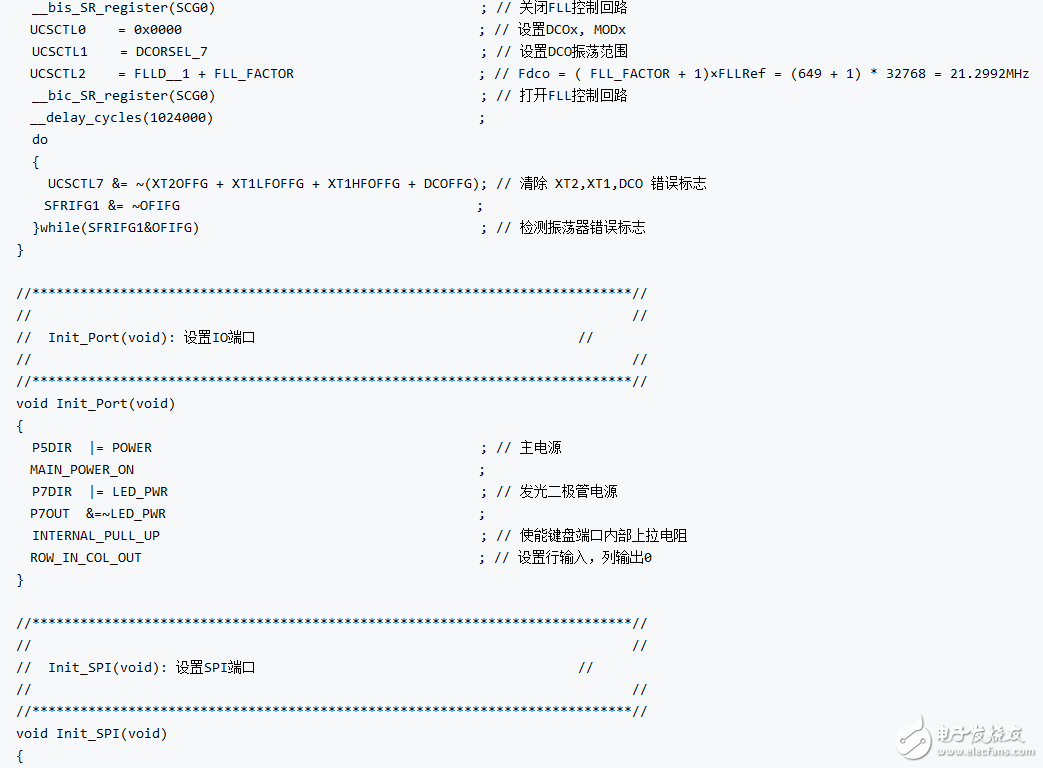
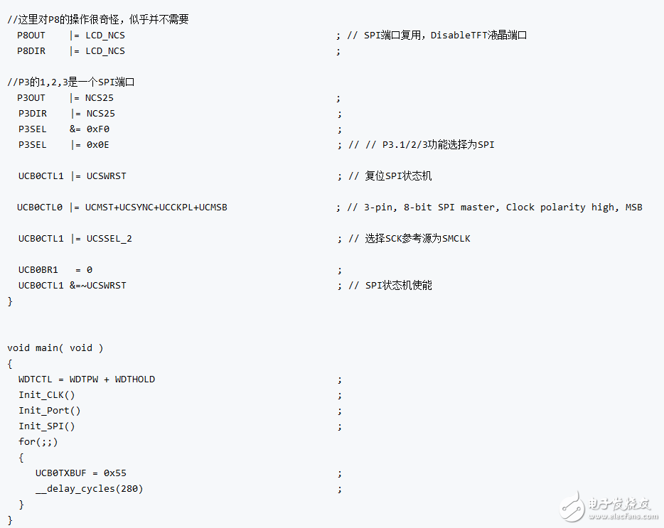
SPI通信基本例程
例程及解释如下:

鉴于CSDN的Markdown代码高亮做的实在是……唉,这里贴一个容易看的吧:
SPI通信代码
SD卡通信方式
以上是给出的例程,SD卡有自己的一套通信方法:
这里引述了:
http://elm-chan.org/docs/mmc/mmc_e.html
当中的内容并予以节选翻译,以便日后查找方面。

MMC卡和SD卡先后推出,接口可以说基本差不多,供电是2.7~3.6V,不要供5V点,否则按照原文说法是“马上坏”(@_@)
SD卡和单片机的电气连接方式如下图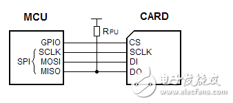 其中有一个上拉电阻有点令人费解
SPI通信模式共有0~3四种,他们的区别是时钟相位和极性。适用于MMC和SD的模式是mode 0(CPHA=0,CPOL=0),但是mode 3多数情况下也管用
SD卡初始化
下面的流程是整个初始化的步骤:
为了避免翻译出现差错,这里也附上英文原文。
上电或卡刚插入时
当供电电压达到2.7V以上时,至少等待1ms,将SPI时钟信号的频率设置在100kHz~400kHz之间,并设置DI和CS(片选信号)为高,并向SCLK输入74个以上时钟脉冲,内存卡将会进入到其默认操作模式并做好接收指令准备
软件复位
保持CS(片选信号)为低电平的情况下,发送一个CMD0指令(就是reset指令,完整指令集的解释附于文后)。SD卡将会在CMD0指令接收之后采样CS信号,如果CS信号为低电平,SD卡将会进入SPI模式,并回复0x01。由于CMD0必须作为:“原生指令”(Native Command)发送,所以CRC部分必须有一个有效(valid)的值(译者注:原生指令中,CRC是固定格式中的一个部分,这里的有效指的是占位还是必须要校验计算不清楚,还要再次确认,这里,CRC作为一个校验位应该和串口的奇偶校验差不多,是只需要选择控制位就可以的,并不需要单独编程计算)。一旦SD卡进入SPI模式之后,这个CRC部分将不再被使用,也不会再被检查。所以,命令中的CRC可以相对固定,但是这个固定值要能够在发送CMD0 和 CMD8 这两个命令(命令参数argument为0的情况下)时保证正确(CMD0的正确CRC,在argument为0的时候是0x95,CMD8待查)。
另外CRC这个特征也可以使用CMD59进行切换,(切换什么和怎样切换没有详细交代)。
补充说明:CMD8命令的稍微详细一些的介绍可以参看:
百度文库
Power ON or card insersion
After supply voltage reached 2.2 volts, wait for one millisecond at least. Set SPI clock rate between 100 kHz and 400 kHz. Set DI and CS high and apply 74 or more clock pulses to SCLK. The card will enter its native operating mode and go ready to accept native command.
Software reset
Send a CMD0 with CS low to reset the card. The card samples CS signal on a CMD0 is received successfully. If the CS signal is low, the card enters SPI mode and responds R1 with In Idle State bit (0x01)。 Since the CMD0 must be sent as a native command, the CRC field must have a valid value. When once the card enters SPI mode, the CRC feature is disabled and the CRC is not checked by the card, so that command transmission routine can be written with the hardcorded CRC value that valid for only CMD0 and CMD8 with the argument of zero. The CRC feature can also be switched with CMD59.
初始化
SD卡在空闲状态下,只接受CMD0,CMD1,ACMD41,CMD58以及CMD59这几个指令,而拒绝其它任何指令。这是,读取OCR寄存器并检查卡片的工作电压范围(似乎通过CMD58进行查询),如果供电超出范围要弹出SD卡。
卡片在接收到CMD1命令时启动初始化流程,主控芯片需要持续发送CMD1并检测回复以确定初始化过程完成。R1回复从0x01变为0x00(Idle State bit 清零)时,意味着初始化成功。初始化过程可能需要数百ms(卡片存储空间越大时间越长),所以需要考虑一个判定超时的阈值。
Idle State bit 清零之后,一般的读写命令就可以执行了。此外因为在对SDC进行操作时,ACMD41被推荐代替CMD1,所以首先尝试发送ACMD41,被拒绝之后再试CMD1,这样的一个流程在理想状况下应该能够适应所有的两种卡。
Initialization
In idle state, the card accepts only CMD0, CMD1, ACMD41,CMD58 and CMD59. Any other commands will be rejected. In this time, read OCR register and check working voltage range of the card. In case of the system sypply voltage is out of working voltage range, the card must be rejected. Note that all cards work at supply voltage range of 2.7 to 3.6 volts at least, so that the host contoller needs not check the OCR if supply voltage is in this range. The card initiates the initialization process when a CMD1 is received. To detect end of the initialization process, the host controller must send CMD1 and check the response until end of the initialization. When the card is initialized successfuly, In Idle State bit in the R1 response is cleared (R1 resp changes 0x01 to 0x00)。 The initialization process can take hundreds of milliseconds (large cards tend to longer), so that this is a consideration to determin the time out value. After the In Idle State bit cleared, generic read/write commands will able to be accepted.
Because ACMD41 instead of CMD1 is recommended for SDC, trying ACMD41 first and retry with CMD1 if rejected, is ideal to support both type of the cards.
SCLK频率应该设置的尽可能快,这样可以使得读写的表现更好(应该是速度更快吧)。CSD寄存器中的TRAN_SPEED区域标明了卡片的最大时钟频率。大部分情况下,MMC为20MHz,SDC则为25MHz。注意时钟频率可以是在这两个值之间的值,没有中间出现开集的其它限制。
在2GB卡上,初始的读写 block length可能是1024,所以block size应该被重新初始化到512(使用CMD16命令)以配合FAT文件系统的工作。
The SCLK rate should be changed to fast as possible to maximize the read/write performance. The TRAN_SPEED field in the CSD register indicates the maximum clock rate of the card. The maximum clock rate is 20MHz for MMC, 25MHz for SDC in most case. Note that the clock rate will able to be fixed to 20/25MHz in SPI mode because there is no open-drain condition that restricts the clock rate.
The initial read/write block length can be set 1024 on 2GB cards, so that the block size should be re-initialized to 512 with CMD16 to work with FAT file system.
初始化 high-capacity cards (不知道高级在什么地方)
在发送给卡片一个CMD0指令使其进入空闲模式后,在初始化之前发送一个CMD8(语句为0x000001AA,需要有正确的校验位CRC)。如果CMD8被拒绝(表现是会回复一个命令错误提示0x05),那么这个卡片是一个SDC一代卡或者MMC三代卡。如果命令被接受,会收到一个R7回复(R1(0x10)+32位返回值)。这个32位返回值的低12位意味着这个卡是一个SDC二代卡。(接着又絮叨了一遍电压范围的事儿,似乎没什么意义)。在确认之后,启动初始化:利用带HCS flag(bit30)的ACMD41命令。后面似乎讲的是如果这个bit 30 被置位,则这个卡就是众所周知的SDHC/SDXC卡(但是it is set当中的这个it指的是什么还是有些拿不准)。以下描述的数据读取/写入操作是按照block寻址的而非按照byte寻址。数据block大小固定在512bytes。
Initializing high-capacity cards
After the card enters idle state with a CMD0, send a CMD8 with argument of 0x000001AA and correct CRC prior to initialization process. If the CMD8 is rejected with illigal command error (0x05), the card is SDC version 1 or MMC version 3. If accepted, R7 response (R1(0x01) + 32-bit return value) will be returned. The lower 12 bits in the return value 0x1AA means that the card is SDC version 2 and it can work at voltage range of 2.7 to 3.6 volts. If not the case, the card should be rejected. And then initiate initialization with ACMD41 with HCS flag (bit 30)。 After the initialization completed, read OCR register with CMD58 and check CCS flag (bit 30)。 When it is set, the card is a high-capacity card known as SDHC/SDXC. The data read/write operations described below are commanded in block addressing insted of byte addressing. The size of data block at block addressing mode is fixed to 512 bytes
-
MSP430F5438A的内部看门狗属于硬件狗,还是软件狗?2012-11-21 0
-
MSP430F5438A BSL烧录方法及工具2013-02-19 0
-
msp430f5438a单片机系统版2013-07-24 0
-
使用msp430F5438A采集交流信号2013-08-10 0
-
msp430f5438a中对其内部RAM的读写2014-07-16 0
-
MSP430f5438A频率怎么设置为32MHz2014-07-20 0
-
msp430F5438A程序汇总2014-07-26 0
-
msp430f5438a的中文资料2014-08-21 0
-
谁能分享MSP430F5438A的库啊,谢谢啦!2015-05-19 0
-
MSP430F5438A2015-10-25 0
-
MSP430F5438A中文书签2017-08-14 0
-
使用MSP430F5438A驱动OV7670的简单程序概述2019-07-09 0
-
MSP430F5438A数据手册2015-11-09 2394
-
MSP430F5438A资料包下载2018-01-05 1064
全部0条评论

快来发表一下你的评论吧 !
