

CAD教程之电缆装配的绘制(英文版)
EDA/IC设计
描述
Most electronic engineers work on products that require Printed Circuit Board designs to be interconnected by cable assemblies. As you might have already noticed, some dedicated tools that primarily focus on designing cable assemblies, while powerful, are quite expensive and beyond the scope of just creating a simple cable design. Most of the industries they are focusing on are automotive, HVAC, and aerospace firms. So you inquire yourself, what is the best alternative? The answer is simply in front of you, utilize your ECAD tool to create the cable assembly!
When working in Altium Designer, I acknowledge all I can do within the tool; I can create my schematic layouts and PCB layouts, I can manage libraries in many ways, and I can control document sources through Version Control. But there are often other questions that come to mind:
What if I wanted to create a design that will determine what the connections are going to be like through a cable?
How can I trace where signals are going, through a designed cable, in an automated way - and how can the design software help?
How can I quickly and effectively generate a detailed cable assembly drawing for the shop floor?
The answer is, use the Altium Designer schematic editor! You can generate very detailed cable drawings with the assistance of importing DXF/DWG files. For example, you can import mechanical drawings of connector heads or crimps that are will be needed for assembly. This way, the assembler can have the life-like drawing to refer to while building the cable. Below is a sample of such a cable drawing:
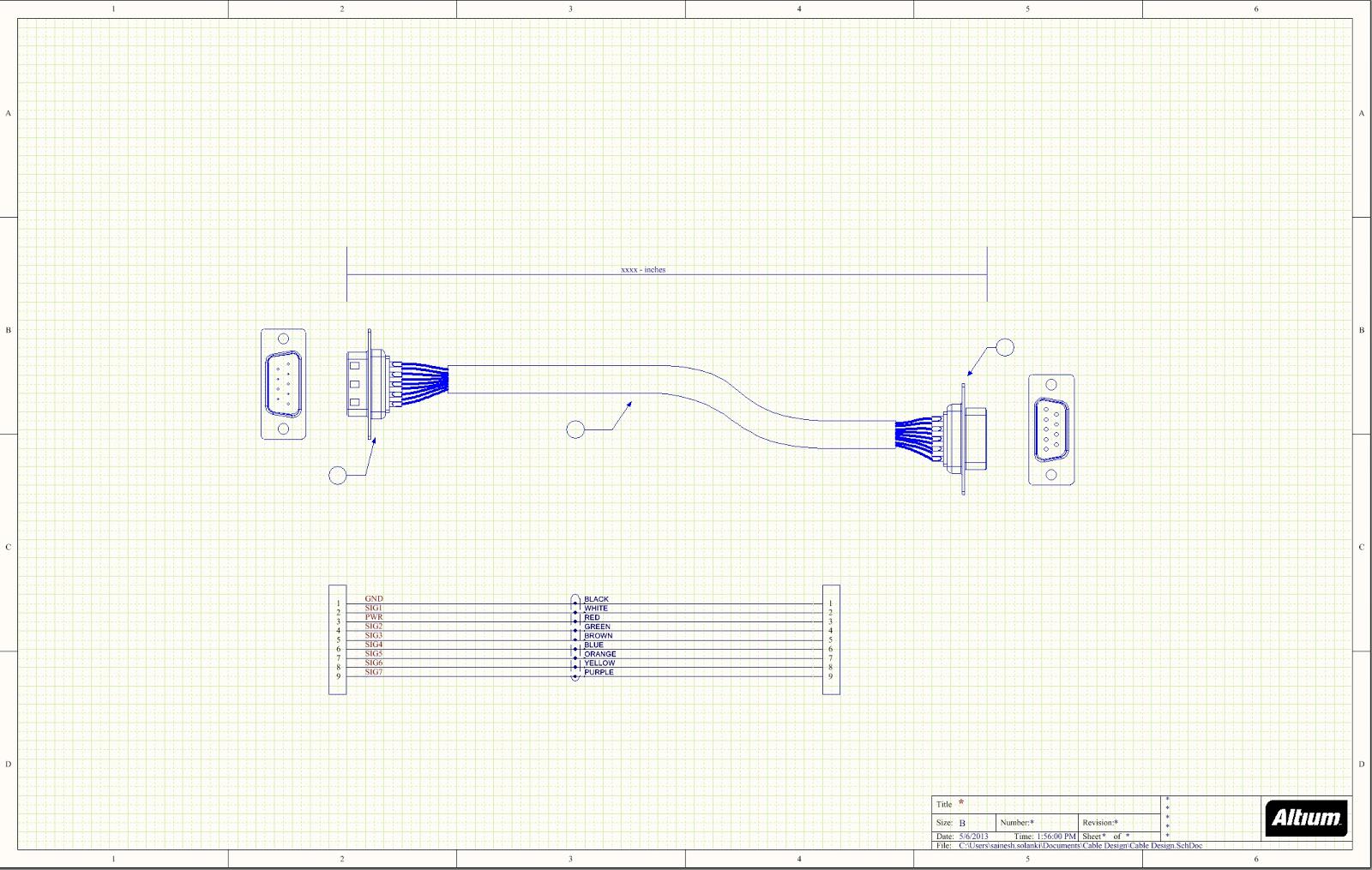
Figure 1. Example Cable Assembly Drawing.
As an example here (see Figure 1), we have a scaled length mechanical cable drawing, with two 1:1 sized connectors, one at each end. Below the mechanical drawing is the schematic representation of it using schematic symbols for the connectors, joined with wires. Within this schematic symbol diagram, you can see that net labels are linked to each connection. The bubbles with arrows (leader notes) represent a line item that you can refer to within the Bill of Materials. Once you have written your assembly notes, you can then send the ready drawing to the assembly house that makes your cables.
Through my own real-world experience, and in collaboration with other work friends, we came up with a robust and powerful methodology for cable design in Altium Designer schematics that takes care of these needs. So, throughout this blog series, I want to share with you:
How to generate the library parts as the building blocks of the cable assembly.
How to use the library parts to generate a complete and well drawn cable assembly.
How to prep and finalize the cable drawing to create your labels and generate outputs to hand-off to the manufacturer.
The first step is how can I get my parts placed as shown in the diagram? The simple answer is to create a multi-part library. What the library will encompass is the cables, connector heads, crimps, and any other mechanical drawing along with the schematic symbol. This will be further discussed in my next installment (part 2) of the Cable Assembly Blog Series.
-
labview 2011的英文版2012-10-12 0
-
求MULTISIM 10.0 英文版2013-04-27 0
-
labview 英文版2013-09-26 0
-
电路布线经验(英文版)2017-02-12 0
-
pscad详细教程上册(英文版)2019-01-10 0
-
CAD教程之CAD序号绘制注意事项2021-01-27 0
-
CAD中怎么绘制连续的导线?2021-02-08 0
-
CAD如何绘制房间排序2021-02-26 0
-
分享10个cad绘制草图的技巧2018-01-12 14240
-
用CAD原理图绘制电缆装配技巧(英文版)2018-06-16 2258
-
CAD教程之CAD怎么画绘制同心圆详细资料说明2018-12-06 1116
-
CAD教程之如何使用CAD编辑器中怎么绘制一个立体的彩色球体2018-12-19 641
-
CAD教程之如何在CAD编辑器中绘制一份表格2018-12-27 993
-
电子CAD原理图绘制题目集2021-03-22 1342
-
如何用CAD绘制漂亮电气图2021-03-30 8036
全部0条评论

快来发表一下你的评论吧 !
