

TI CC1352R多波段多协议无线MCU解决方案
电子说
描述
TI公司的CC1352R是多协议《1GHz和2.4GHz无线MCU,具有非常低的RF和微控制器(MCU)电流,小于μA的睡眠电流和高达80KB RAM,提供极好电池寿命和工作在小型纽扣电池,其专用的无线电控制器(Arm® Cortex®-M0)能处理存储在ROM或RAM的低档RF协议指令,具有极好的灵敏度和鲁棒性能(robustness),主要用在无线M总线,IEEE802.15.4g,6LoWPAN,Zigbee®, KNX RF, Wi-SUN®, Bluetooth® 5低能量系统和有所有全系统以及智能电网和自动读表,无线传感器网络,工业和无线卫生保健应用,能量收获,家庭和建筑物自动化。本文介绍了CC1352R主要特性,框图,物联网(IoT)网关参考设计TIDC-01002主要特性,硬件框图和15.4堆栈传感器-云参考设计软件框图,电路图和PCB设计图。
CC1352R (PREVIEW) SimpleLink Multi-Band CC1352R Wireless MCU
The CC1352R device is a multiprotocol Sub-1 and 2.4-GHz wireless MCU targeting Wireless M-Bus, IEEE802.15.4g, IPv6-enabled smart objects (6LoWPAN), Thread, Zigbee®, KNX RF, Wi-SUN®, Bluetooth® 5low energy, and proprietary systems.CC1352R is a member of the CC26xx and CC13xx family of cost-effective, ultra-low power, 2.4-GHz andSub-1 GHz RF devices. Very low active RF and microcontroller (MCU) current, in addition to sub-μA sleepcurrent with up to 80KB of RAM retention, provide excellent battery lifetime and allow operation on smallcoin-cell batteries and in energy-harvesting applications.
The CC1352R device combines a flexible, very low-power RF transceiver with a powerful 48-MHz Arm®Cortex®-M4F CPU in a platform supporting multiple physical layers and RF standards. A dedicated RadioController (Arm® Cortex®-M0) handles low-level RF protocol commands that are stored in ROM or RAM,thus ensuring ultra-low power and great flexibility. The low power consumption of the CC1352R devicedoes not come at the expense of RF performance; the CC1352R device has excellent sensitivity androbustness (selectivity and blocking) performance.
The CC1352R device is a highly integrated, true single-chip solution incorporating a complete RF systemand an on-chip DC/DC converter.Sensors can be handled in a very low-power manner by a programmable, autonomous ultra-low powerSensor Controller CPU with 4KB of SRAM for program and data. The Sensor Controller, with its fastwake-up and ultra-low-power 2-MHz mode is designed for sampling, buffering, and processing bothanalog and digital sensor data; thus the MCU system can maximize sleep time and reduce active power.
The CC1352R device is part of the SimpleLink™ microcontroller (MCU) platform, which consists of Wi-Fi®,Bluetooth® low energy, Thread, Zigbee, Sub-1 GHz MCUs, and host MCUs, which all share a common,easy-to-use development environment with a single core software development kit (SDK) and rich tool set.A one-time integration of the SimpleLink platform enables you to add any combination of the portfolio’sdevices into your design, allowing 100 percent code reuse when your design requirements change.
CC1352R主要特性:
• Microcontroller
– Powerful Arm® Cortex®-M4F Processor
– EEMBC CoreMark® Score: 148
– Clock Speed Up to 48 MHz
– 352KB of In-System Programmable Flash
– 256KB of ROM for Protocols and Firmware
– 8KB of Cache SRAM (Available as General-Purpose RAM)
– 80KB of Ultra-Low Leakage SRAM
– 2-Pin cJTAG and JTAG Debugging
– Supports Over-the-Air Upgrade (OTA)
• Ultra-Low Power Sensor Controller With 4KB ofSRAM
– Sample, Store, and Process Sensor Data
– Operation Independent From System CPU
– Fast Wake-Up for Low-Power Operation
• TI-RTOS, Drivers, Bootloader, Bluetooth® 5 lowenergy Controller, and IEEE 802.15.4 MAC inROM for Optimized Application Size
• RoHS-Compliant Package
– 7-mm × 7-mm RGZ VQFN48 (28 GPIOs)
• Peripherals
– Digital Peripherals Can be Routed to Any GPIO
– 4× 32-Bit or 8× 16-Bit General-Purpose Timers
– 12-Bit ADC, 200 kSamples/s, 8 Channels
– 2× Comparators With Internal Reference DAC(1× Continuous Time, 1× Ultra-Low Power)
– Programmable Current Source
– 2× UART
– 2× SSI (SPI, MICROWIRE, TI)
– I2C
– I2S
– Real-Time Clock (RTC)
– AES 128- and 256-bit Crypto Accelerator
– ECC and RSA Public Key Hardware Accelerator
– SHA2 Accelerator (Full Suite Up to SHA-512)
– True Random Number Generator (TRNG)
– Capacitive Sensing, Up to 8 Channels
– Integrated Temperature and Battery Monitor
• External System
– On-Chip Buck DC/DC Converter
• Low Power
– Wide Supply Voltage Range: 1.8 V to 3.8 V
– Active-Mode RX: 5.7 mA
– Active-Mode TX at +10 dBm: 14 mA (868 MHz)
– Active-Mode MCU 48 MHz (CoreMark):2.82 mA (59 μA/MHz)
– Sensor Controller 16-Hz Flow Metering:1.7 μA
– Sensor Controller 100-Hz Comp A Reading:1.5 μA
– Sensor Controller, 1-Hz ADC Sampling:1 μA
– Standby: 0.8 μA (RTC on, 80KB RAM and CPURetention)
– Shutdown: 105 nA (Wakeup on External Events)
• Radio Section
– Dual-Band Sub-1 GHz and 2.4-GHz RFTransceiver Compatible With Bluetooth 5 low
energy and IEEE 802.15.4 PHY and MAC
– Excellent Receiver Sensitivity:
–125 dBm for SimpleLink Long Range,
–109 dBm at 50 kbps, –103 dBm for Bluetooth 5low energy Coded
– Excellent Selectivity: 52 dB at 50 kbps
– Programmable Output Power Up to +14 dBm(Sub-1 GHz) and +5 dBm (2.4 GHz)
– Suitable for Systems Targeting Compliance WithWorldwide Radio Frequency Regulations
– ETSI EN 300 220, EN 300 328, EN 303 131,EN 303 204 (Europe)
– EN 300 440 Class 2 (Europe)
– FCC CFR47 Part 15 (US)
– ARIB STD-T108 and STD-T66 (Japan)
– Wide Standard Support
• Development Tools and Software
– LAUNCHXL-CC1352R1 Development Kit
– SimpleLink CC13X2 Software Development Kit
– SmartRF™ Software Studio for Simple RadioConfiguration
– Sensor Controller Studio for Building Low-PowerSensor Applications
CC1352R应用:
• 433-, 450 to 470-, 868-, 902 to 928-, 1090-, and2400 to 2480-MHz ISM and SRD Systems (1)With Down to 4 kHz of Receive Bandwidth
• Smart Grid and Automatic Meter Reading
– Water, Gas, and Electricity Meters
– Heat Cost Allocators
– Gateways
• Wireless Sensor Networks
– Long-Range Sensor Applications
• Industrial
– Asset Tracking and Management
– Factory Automation
– Remote Display
• Wireless Healthcare Applications
• Energy Harvesting Applications
• Electronic Shelf Label (ESL)
• Home and Building Automation
– Wireless Alarms and Security Systems
– Locks
– Lightning Control
– Motion Detectors
– Connected Appliances
– HVAC
– Garage Door Openers
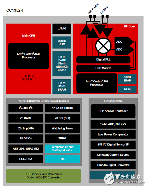
图1.CC1352R功能框图
物联网(IoT)网关参考设计TIDC-01002
Sub-1 GHz Embedded Sensor to Cloud Industrial Internet of Things (IoT) Gateway Reference Design The TIDC-01002 design demonstrates how to connectsensors to the cloud over a long-range, Sub-1 GHzwireless network, which may be used in industrialsettings, such as building control and asset tracking.
This TI Design is powered through a TI SimpleLink™CC3220 processor and SimpleLink ultra-low-power(ULP), Sub-1 GHz CC13x0 and CC13x2 devices. Thereference design pre-integrates the TI 15.4-Stack partof the SimpleLink CC13xx software development kits(SDK) and SimpleLink CC3220 SDK, which are part ofthe TI SimpleLink MCU platform, providing a unifiedsoftware experience across TI low-power, wired, andwireless MCUs.
The TIDC-01002 provides a reference for creating an industrial, Internet of things (IoT) gateway that iscapable of connecting a network of wireless sensors to an enterprise cloud provider. In this referencedesign, a long-range, low-power wireless network, made up of Sub-1 GHz CC13x0 or CC13x2 devices(both are supported) that run the TI 15.4-Stack-based application, can be connected to multiple cloudservice providers, such as IBM Watson IoT®, AWS IoT, and so on. An online dashboard is provided, which allows users visualize the real-time sensor data as well as send actuation commands from anywhere inthe world using an Internet-connected device with a web browser.
This reference design provides a list of suggested hardware, schematics, and foundational software toquickly begin IoT product development. The design also provides the ability to visualize the data inside alocal network without connecting to a cloud service. The software design is created to be flexible, toenable other cloud service providers of choice.
This reference design enables IoT in numerous applications, such as building security gateways, door andwindow sensor networks, asset management and tracking, and other IoT-enabled home and industrialautomation applications.
The connection between the wireless sensor network and the cloud is made possible by the TI SimpleLinkCC3220 device on the CC3220SF LaunchPad™ development platform. On one side, the CC3220 isconnected to a Sub-1 GHz device acting as the central node in the wireless network, and on the otherside, the device is connected to a cloud service such as IBM Watson IoT or AWS IoT using Wi-Fi®。 Thesetwo connections allow the CC3220 device to act as a gateway to get the sensor messages from the Sub-1GHz wireless network to the cloud and to get the actuation requests from the cloud dashboard sent backto the Sub-1 GHz wireless network.
Due to the long-range and low-power capabilities of the Sub-1 GHz sensors, this reference design may beuseful for any application that would benefit from distributed sensing. This reference design provides anexample that gives the ability to visualize or actuate tens or hundreds of sensors while only needing onegateway device, the SimpleLink CC3220, to be connected to the Internet.
物联网(IoT)网关参考设计TIDC-01002主要特性:
• Large Network-to-Cloud Connectivity EnablingLong Range, Up to 1 km (Line of Sight)
• Facilitates Designer ’ s System Compliance WithIEEE 802.15.4e/g by Using TI 15.4-Stack
• Based on TI Tested Hardware Designs EnablingQuick Time to Market With Out-of-the-Box, Readyto-Use Demonstration Software
• Implementation Based on Portable OperatingSystem Interface (POSIX), Allows for Easy
Portability Across TI Internet ConnectedMicrocontrollers (MCUs)
• Supports Star Networks
• ULP Sensor Nodes
物联网(IoT)网关参考设计TIDC-01002应用:
• Building Security Gateway
• Door and Window Sensor Networks
• HVAC Gateway
• Asset Management and Tracking
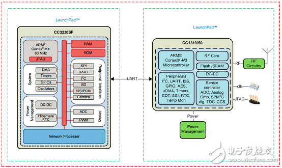
图2.物联网(IoT)网关参考设计TIDC-01002框图
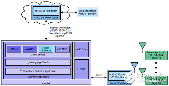
图3.TI 15.4堆栈传感器-云参考设计软件框图
图4.CC1350 LaunchPan板外形图
图5.CC1350 和CC3220SF LaunchPan开发套件外形图
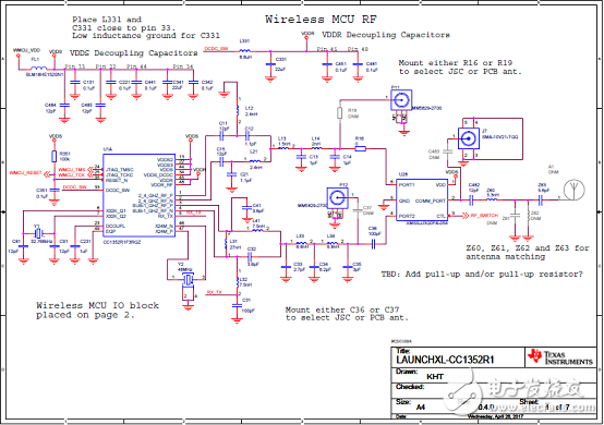
图6.CC1350 LaunchPan板电路图(1)
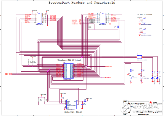
图7.CC1350 LaunchPan板电路图(2)
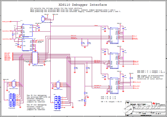
图8.CC1350 LaunchPan板电路图(3)
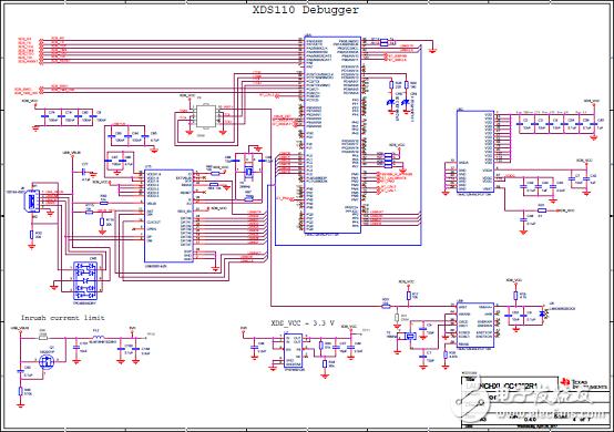
图9.CC1350 LaunchPan板电路图(4)
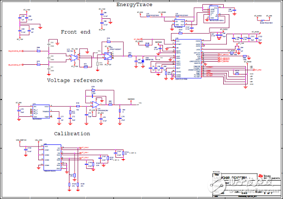
图10.CC1350 LaunchPan板电路图(5)
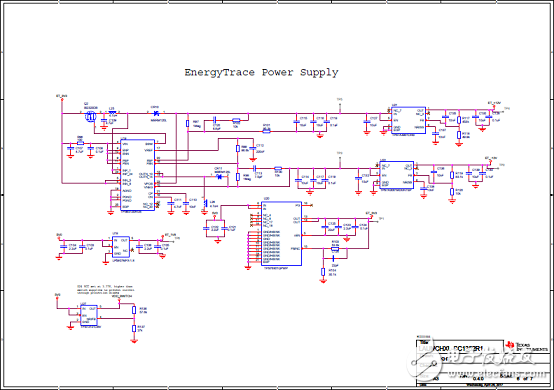
图11.CC1350 LaunchPan板电路图(6)
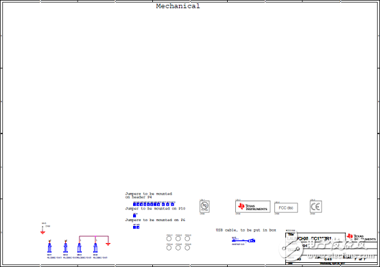
图12.CC1350 LaunchPan板电路图(7)
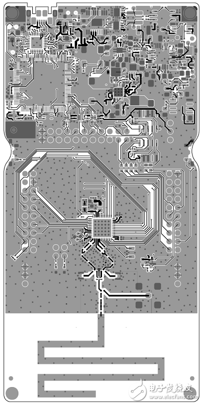
图13.CC1350 LaunchPan板PCB设计图(1)
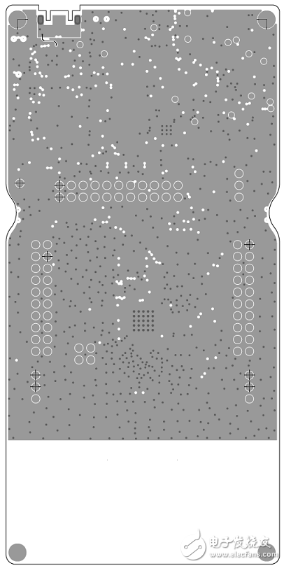
图14.CC1350 LaunchPan板PCB设计图(2)
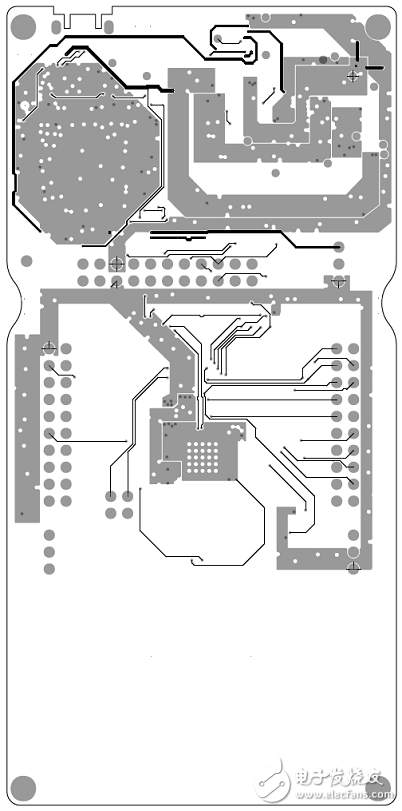
图15.CC1350 LaunchPan板PCB设计图(3)
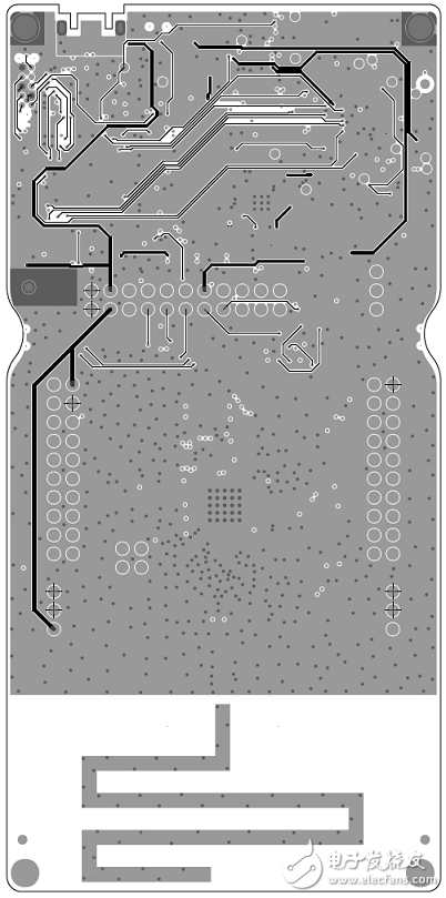
图16.CC1350 LaunchPan板PCB设计图(4)
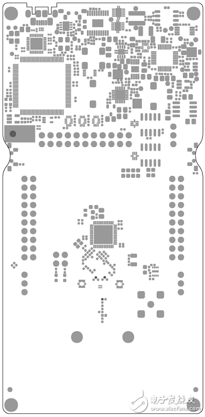
图17.CC1350 LaunchPan板PCB设计图(5)
图18.CC1350 LaunchPan板PCB设计图(6)
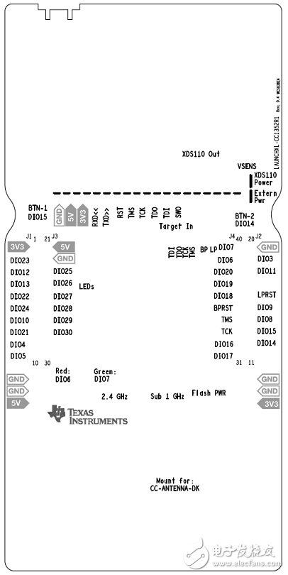
图19.CC1350 LaunchPan板PCB设计图(7)
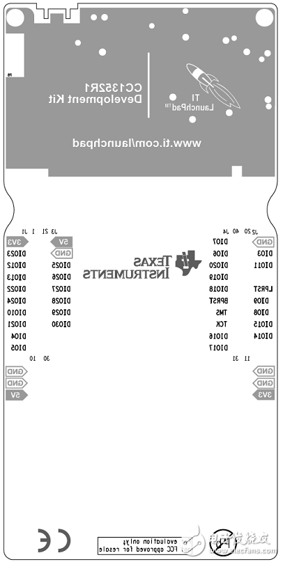
图20.CC1350 LaunchPan板PCB设计图(8)
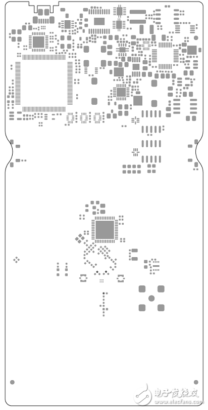
图21.CC1350 LaunchPan板PCB设计图(9)
图22.CC1350 LaunchPan板PCB设计图(10)
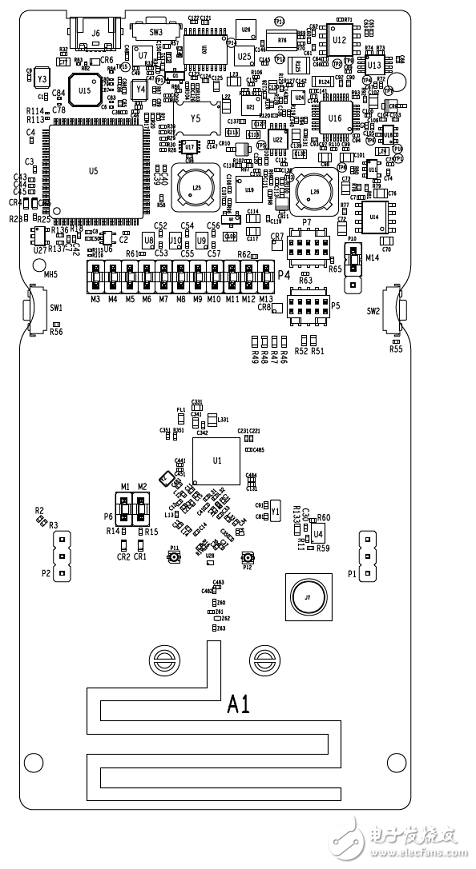
图23.CC1350 LaunchPan板PCB设计图(11)
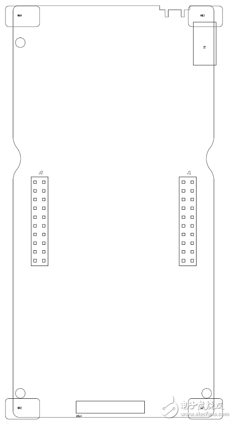
图24.CC1350 LaunchPan板PCB设计图(12)
-
CC2650 SimpleLink™ 多标准无线 MCU2016-02-25 0
-
TI CC2640R2F低功耗无线MCU可适用于这些行业领域!2017-02-15 0
-
新型SimpleLink™蓝牙低功耗CC2640R2F无线MCU必知2017-04-01 0
-
TI CC2640R2F、CC2640、CC2541 MCU 特性介绍与对比2017-09-28 0
-
TI CC2640R2F MCU方案设计与典型应用2017-09-29 0
-
Bluetooth®5将解锁SimpleLink™CC2640R2F无线MCU的电源2018-08-03 0
-
TI CC2640R2F、CC2640、CC2541 MCU特性介绍与区别2018-08-19 0
-
分享一款不错的RC1180-KNX:多协议无线应用解决方案2021-05-26 0
-
基于TI的无线MCU芯片开发出的无线麦克风解决方案2022-11-03 0
-
CC1352R SimpleLink 多频带 CC1352R 无线 MCU2018-11-02 744
-
CC1352R SimpleLink多频带无线MCU2020-03-25 1328
-
贸泽电子开售TI CC1352R LaunchPad SensorTag2020-03-04 806
-
信驰达推出TI CC1352P7双频段多协议模块RF-TI1352P22023-11-02 248
全部0条评论

快来发表一下你的评论吧 !
