

[原创] TI DS90UB960-Q1ADAS 8路传感器集线器参考设计TIDA-01413
嵌入式技术
描述
TI公司的DS90UB960-Q1是多种传感器集线器,能从四个不同的视频数据流通过FPD-Link III接口接收串行化传感器数据.和DS90UB953-Q1配对时,它能以60Hz帧速率接收传感器诸如支持全HD 1080p/2MP分辨率的图像.DS90UB960-Q1包括四个FPD-Link III解串器,每个可通过50-Ω单端同轴或100-Ω差分STP电缆进行连接,而接收均衡器能自动补偿电缆损耗特性,包括随时间的老化.主要用在汽车ADAS如后视照相机(RVC),环绕视图系统(SVS)和照相机监测系统(CMS),前视照相机(FC),驾驶员监测系统(DMS)以及卫星RADAR等以及安全和监控.本文介绍了DS90UB960-Q1主要特性,功能框图,应用电路,以及具有两个4Gbps四路串-并行变换器的ADAS 8路传感器集线器参考设计TIDA-01413主要特性,框图,电路图,材料清单和PCB设计图.
The DS90UB960-Q1 is a versatile sensor hubcapable of connecting serialized sensor data receivedfrom four independent video data streams through anFPD-Link III interface. When paired with aDS90UB953-Q1 serializer, the DS90UB960-Q1receives data from sensors such as imagerssupporting full HD 1080p/2MP resolution at 60-Hzframe rates. Data is received and aggregated into aMIPI CSI-2 compliant output for interconnect to a downstream processor. A second MIPI CSI-2 outputport is available to provide additional bandwidth, oroffers a second replicated output for data-logging andparallel processing.
The DS90UB960-Q1 includes four FPD-Link IIIdeserializers, each enabling a connection throughcost-effective 50-Ω single-ended coaxial or 100-Ωdifferential STP cables. The receive equalizersautomatically adapt to compensate for cable losscharacteristics, including degradation over time.
Each of the FPD-Link III interfaces also includes aseparate low latency bidirectional control channel thatcontinuously conveys I2C, GPIOs, and other controlinformation. General-purpose I/O signals such asthose required for camera synchronization and diagnostics features also make use of thisbidirectional control channel.The DS90UB960-Q1 is AEC-Q100 qualified forautomotive applications and is offered in a costeffectiveand space-saving 64-pin VQFN package.
DS90UB960-Q1主要特性:
1• AEC-Q100 Qualified for Automotive Applications:
– Device Temperature Grade 2: –40℃to +105℃Ambient Operating Temperature Range
• Quad 4.16 GbpsDeserializer Hub AggregatesData From up to 4 Sensors Simultaneously
• Supports 2-Megapixel Sensors With Full HD
1080p Resolution at 60-Hz Frame Rate
• Precise Multi-Camera Synchronization
• MIPI DPHY Version 1.2 / CSI-2 Version 1.3Compliant
– 2 × MIPI CSI-2 Output Ports
– Supports 1, 2, 3, 4 Data Lanes per CSI-2 port
– CSI-2 Data Rate Scalable for 400 Mbps / 800Mbps / 1.2 Gbps / 1.5 Gbps / 1.6 Gbps per Data Lane
– Port Replication Mode
• Ultra-Low Data and Control Path Latency
• Supports Single-Ended Coaxial Including Powerover-Coax (PoC) or Shielded Twisted-Pair (STP)Cable
• Adaptive Receive Equalization
• Dual I2C Ports With Fast-Mode Plus up to 1 Mbps
• Flexible GPIOs for Sensor Synchronization andDiagnostics
• Compatible With DS90UB953-Q1, DS90UB935-Q1,
DS90UB933-Q1, DS90UB913A-Q1Serializers
• Internal Programmable Precision Frame SyncGenerator
• Line Fault Detection and Advanced Diagnostics
DS90UB960-Q1应用:
• Automotive ADAS
– Rear View Cameras (RVC)
– Surround View Systems (SVS)
– Camera Monitoring Systems (CMS)
– Forward Vision Cameras (FC)
– Driver Monitoring Systems (DMS)
– Satellite RADAR, Time-of-Flight (ToF), andLIDAR Sensors Modules
– Sensor Fusion
• Security and Surveillance
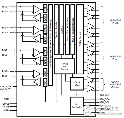
图1.DS90UB960-Q1功能框图
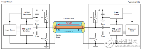
图2.同轴电缆供电(PoC)系统框图
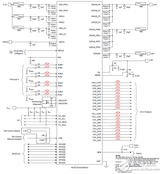
图3.典型连接图(同轴)
图4.典型连接图(STP/STQ)
图5.四个DS90UB953-Q1传感器数据连接CSI-2两端口
图6.ADAS系统框图
具有两个4Gbps四路串-并行变换器的ADAS 8路传感器集线器参考设计TIDA-01413
This sensor fusion hub reference design allows theconnection of up to four 2-megapixel cameras and upto four radar modules over coaxial cable. This designutilizes these coaxial cables to provide power, backchannelcommunication, and clock synchronization tothe sensors. The two 4-Gbps FPD-Link III quaddeserializers support dual-outputs of the MobileIndustry Processor Interface (MIPI) Camera SerialInterface-2 (CSI-2) over a Samtec connector toapplication processors.
参考设计TIDA-01413主要特性:
• Accepts 8 High-Speed Data Inputs Over FPD-LinkIII Synchronization Capability
• Provides Wide-Range Supply Voltage for Power
Over Coax (4 V to 14 V)
• Directly Connects to TDA2Plus EVM Through CSI-2 Interface
• Car Battery can Directly Supply Board Power WithProtection From Reverse Current
• Utilizes MSP430™ Microcontroller (MCU) toInitialize and Configure Video Pipeline
• Design Compatible With Onboard MCU, WithoutMCU, or With External MCU
• Works With Any Camera That Uses CompatibleFPD-Link III DS90UB953 Serializer
参考设计TIDA-01413应用:
• Advanced Driver Assistance Systems (ADAS)
• Surround View
• CMS and Mirror Replacement
• ADAS Domain Controller
图7.参考设计TIDA-01413外形图
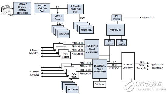
图8.参考设计TIDA-01413框图
图9.参考设计TIDA-01413板顶视图
图10.参考设计TIDA-01413板底视图
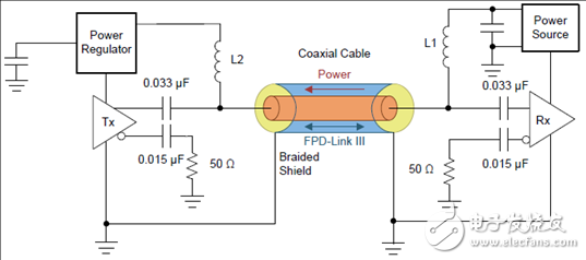
图11.同轴电缆供电框图
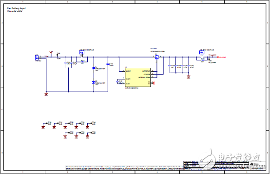
图12.参考设计TIDA-01413电路图(1)
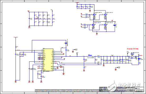
图13.参考设计TIDA-01413电路图(2)
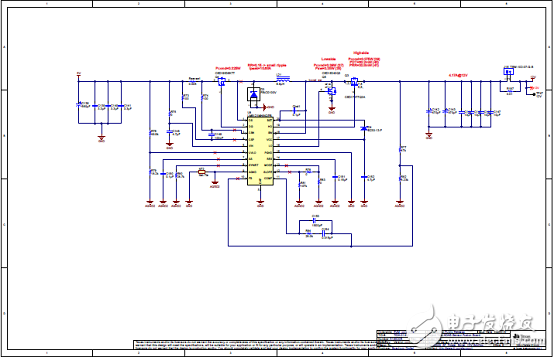
图14.参考设计TIDA-01413电路图(3)
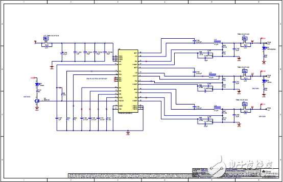
图15.参考设计TIDA-01413电路图(4)
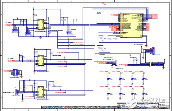
图16.参考设计TIDA-01413电路图(5)
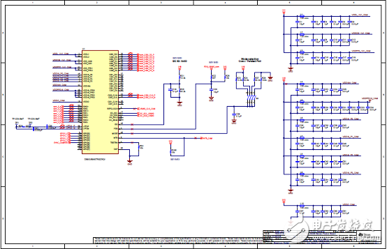
图17.参考设计TIDA-01413电路图(6)
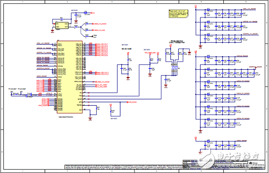
图18.参考设计TIDA-01413电路图(7)
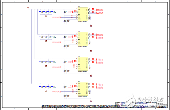
图19.参考设计TIDA-01413电路图(8)
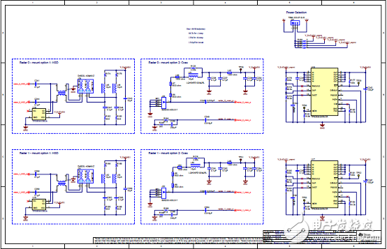
图20.参考设计TIDA-01413电路图(9)
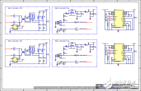
图21.参考设计TIDA-01413电路图(10)
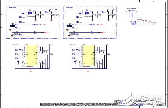
图22.参考设计TIDA-01413电路图(11)
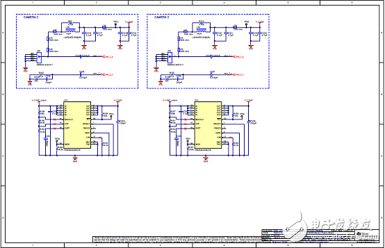
图23.参考设计TIDA-01413电路图(12)
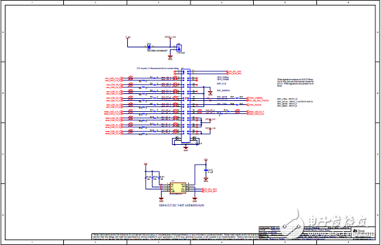
图24.参考设计TIDA-01413电路图(13)
图25.参考设计TIDA-01413电路图(14)
参考设计TIDA-01413材料清单:
图26.参考设计TIDA-01413 PCB设计图(1)
图27.参考设计TIDA-01413 PCB设计图(2)
图28.参考设计TIDA-01413 PCB设计图(3)
图29.参考设计TIDA-01413 PCB设计图(4)
图30.参考设计TIDA-01413 PCB设计图(5)
图31.参考设计TIDA-01413 PCB设计图(6)
图32.参考设计TIDA-01413 PCB设计图(7)
图33.参考设计TIDA-01413 PCB设计图(8)
图34.参考设计TIDA-01413 PCB设计图(9)
图35.参考设计TIDA-01413 PCB设计图(10)
图36.参考设计TIDA-01413 PCB设计图(11)
图27.参考设计TIDA-01413 PCB设计图(12)
详情请见:
和
以及
和
与
snls589b.pdf
- 相关推荐
-
多功能摄像头集线器DS90UB960-Q1数据表2024-03-06 57
-
ADAS多传感器集线器参考设计包括BOM及层图2018-10-08 0
-
ADAS 8通道传感器融合集线器参考设计包括BOM及层图2018-10-24 0
-
用于先进驾驶辅助系统和自主驾驶的集成智能传感器健康监测装置概述2019-07-30 0
-
请问有人用过TI的DS0UB941与DS90UB948作为车机的视频传输吗?2022-09-07 0
-
德州仪器(TI)推出DS90UB913Q串行器与DS90UB914Q解串器2012-08-28 6181
-
多功能摄像头集线器DS90UB964-Q1的主要特性2018-04-17 4651
-
DS90UB949-Q1 DS90UB949-Q1 1080p 双路 FPD-Link III 串行器2018-10-16 864
-
DS90UB929-Q1 DS90UB929-Q1 720p FPD-Link III 串行器2018-10-16 460
-
DS90UB947-Q1 DS90UB947-Q1 1080p 双路 FPD-Link III 串行器2018-10-16 944
-
DS90UB960-Q1 具有两个 CSI-2 输出端口的四路 200 万像素摄像头集线器 FPD-Link III 解串器2018-10-16 705
-
DS90UB934-Q1 DS90UB934-Q1 25MHz 至 100MHz 10/12 位 FPD-Link III 串行器和解串器2018-10-16 587
-
DS90UB954-Q1 DS90UB954-Q1 用于 2.3MP/60fps 摄像机的 FPD-Link III 至 CSI-2 解串器2018-10-16 1141
-
DS90UB914Q-Q1 DS90UB913Q/4Q 10-100MHz 10/12 位 FPD-Link III 串行器/解串器2018-10-16 364
-
DS90UB962-Q1 具有单个 CSI-2 输出的四路 3Gbps FPD-Link III 解串器集线器2019-01-08 1289
全部0条评论

快来发表一下你的评论吧 !
