

TI TPS65987DUSB Type-C和PD控制器解决方案
嵌入式技术
描述
TI公司的TPS65987D是单独使用的USB Type-C和PD控制器,提供了电缆插头和定向检测,是全集成USB供电(USB-PD)管理器件,包括USB-PD控制器,电缆插头和取向检测电路,电源开关,电源管理电路以及数字核等五部分.它通过电缆和在电缆另以端的另外USB Type-C和PD设备进行通信,集成端口电源开关,控制外部大电流端口电源开关和协商不同模式,还能经由GPIO或I2C控制超高速复接器,以支持USB3.0/3.1数据速率和DisplayPort视频.主要用在笔记本电脑,平板电脑和超极本(Ultrabook),坞站系统,DisplayPort和Thunderbolt™系统.本文介绍了TPS65987D主要特性和功能框图,应用案例电路以及评估板USB-C-PD-DUO-EVM主要特性,电路图,材料清单和PCB设计图.
The TPS65987D is a stand-alone USB Type-C andPower Delivery (PD) controller providing cable plugand orientation detection for a single USB Type-Cconnector. Upon cable detection, the TPS65987Dcommunicates on the CC wire using the USB PDprotocol. When cable detection and USB PDnegotiation are complete, the TPS65987D enablesthe appropriate power path and configures alternatemode settings for external multiplexers.
The TPS65987D is a fully-integrated USB Power Delivery (USB-PD) management device providing cable plugand orientation detection for a USB Type-C and PD plug or receptacles. The TPS65987D communicates with thecable and another USB Type-C and PD device at the opposite end of the cable, enables integrated port powerswitch, controls an external high current port power switch, and negotiates alternate modes. The TPS65987Dmay also control an attached super-speed multiplexer via GPIO or I2C to simultaneously support USB3.0/3.1data rates and DisplayPort video.
The TPS65987D is divided into five main sections: the USB-PD controller, the cable plug and orientationdetection circuitry, the port power switches, the power management circuitry, and the digital core.
The USB-PD controller provides the physical layer (PHY) functionality of the USB-PD protocol. The USB-PD datais output through either the C_CC1 pin or the C_CC2 pin, depending on the orientation of the reversible USBType-C cable. For a high-level block diagram of the USB-PD physical layer, a description of its features andmore detailed circuitry, see the USB-PD Physical Layer section.
The cable plug and orientation detection analog circuitry automatically detects a USB Type-C cable plug insertionand also automatically detects the cable orientation. For a high-level block diagram of cable plug and orientationdetection, a description of its features and more detailed circuitry, see the Cable Plug and Orientation Detection section.
The port power switches provide power to the system port through the VBUS pin and also through the C_CC1 orC_CC2 pins based on the detected plug orientation. For a high-level block diagram of the port power switches, adescription of its features and more detailed circuitry, see the Port Power Switches section.
The power management circuitry receives and provides power to the TPS65987D internal circuitry and to theLDO_3V3 output. For a high-level block diagram of the power management circuitry, a description of its featuresand more detailed circuitry, see the Power Management section.
The digital core provides the engine for receiving, processing, and sending all USB-PD packets as well ashandling control of all other TPS65987D functionality. A portion of the digital core contains ROM memory whichcontains all the necessary firmware required to execute Type-C and PD applications. In addition, a section of theROM, called boot code, is capable of initializing the TPS65987D, loading of device configuration information, and loading any code patches into volatile memory in the digital core. For a high-level block diagram of the digitalcore, a description of its features and more detailed circuitry, see the Digital Core section.
The TPS65987D is an I2C slave to be controlled by a host processor (see the I2C Interfaces section), and an SPImaster to write to and read from an optional external flash memory (see the SPI Master Interface section).
The TPS65987D also integrates a thermal shutdown mechanism (see Thermal Shutdown section) and runs off ofaccurate clocks provided by the integrated oscillators (see the Oscillators section).
TPS65987D主要特性:
1• USB Power Delivery (PD) Controller
– USB PD 3.0 Compliant
– Fast Role Swap Support
– Physical Layer and Policy Engine
– Configurable at Boot and Host-Controlled
• USB Type-C Specification Compliant
– Cable Attach and Orientation Detection
– Default, 1.5 A, or 3 A Power Advertisement
– Up to 600-mA VConn Current
• Port Power Switch
– Two 5 V to 20 V, 5-A Bidirectional Switches toor from VBUS
– Up to 10-A Adjustable Current Limiting
– Ideal Diode Reverse Current Protection
– Undervoltage, and Overvoltage Protection
– Slew Rate Control
– 5-V, 600-mA VConn Source
• BC1.2 Support
– Advertisement as DCP and CDP
– Automatic DCP Modes Selection:
– Shorted Mode per BC1.2 and YD/T 1591-2009
– 2.7-V Divider 3 Mode
– 1.2-V Mode
– Data Contact Detect
– Primary and Secondary Detection
• I2C Master Write Control for Alt Mode Muxes andVariable DCDCs
• Alternate Mode Support
– DisplayPort
– Thunderbolt™
• Power Management
– Power Supply from 3.3 V or VBUS Source
– 3.3-V LDO Output for Dead Battery Support
• 7-mm × 7-mm QFN Package
– 0.4-mm Pitch
– 56 Pin
TPS65987D应用:
• Notebook Computers
• Docking Systems
• Tablets and Ultrabooks
• DisplayPort, and Thunderbolt™ Systems
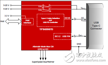
图1.TPS65987D简化电路
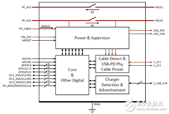
图2.TPS65987D功能框图
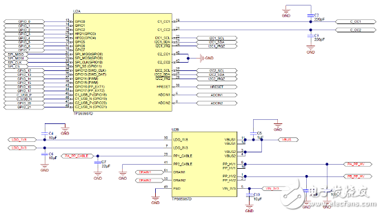
图3.TPS65987D案例电路
评估板USB-C-PD-DUO-EVM
The USB-C-PD-DUO-EVM allows the TPS65987D to enter Power DUO mode where both VBUS PowerPaths are enabled in parallel to allow for half the effective RDSon. The USB-C-PD-DUO-EVM containsboth a Source side and Sink side board to allow users to evaluate Power DUO mode for either a source orsink design. The USB-C-PD-DUO-EVM also allows users to select both the source and sink capabilitiesoffered through the use of the push button switches labeled 5 V, 9 V, 15 V, and 20 V respectively.
图4.评估板USB-C-PD-DUO-EVM外形图
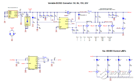
图5.评估板USB-C-PD-DUO-EVM电路图:电源
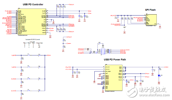
图6.评估板USB-C-PD-DUO-EVM电路图:源PD控制器
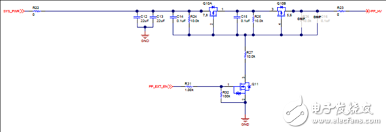
图7.评估板USB-C-PD-DUO-EVM电路图:旁路电源通路
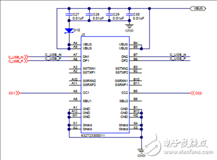
图8.评估板USB-C-PD-DUO-EVM电路图:源Type-C连接器
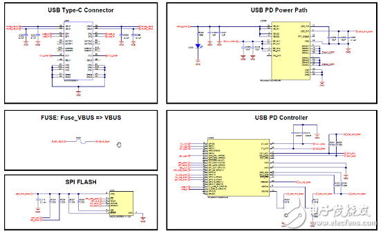
图9.评估板USB-C-PD-DUO-EVM电路图:沉PD控制器
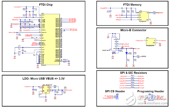
图10.评估板USB-C-PD-DUO-EVM电路图:FTDI
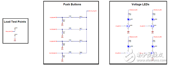
图11.评估板USB-C-PD-DUO-EVM电路图:沉按扭和LED
评估板USB-C-PD-DUO-EVM材料清单:
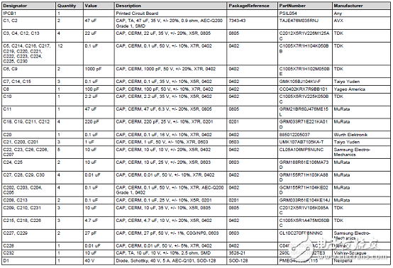
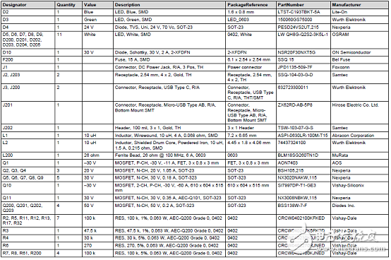
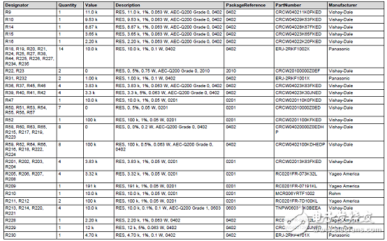
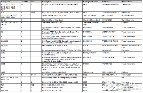
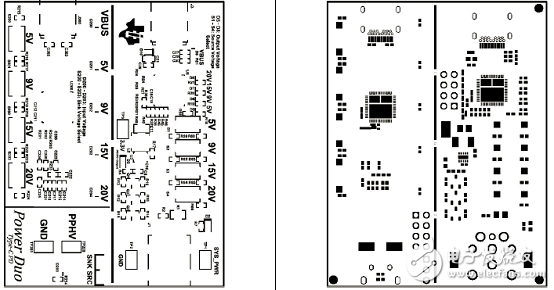
图12.评估板USB-C-PD-DUO-EVM PCB设计图:左:顶层综合;右:顶层焊接
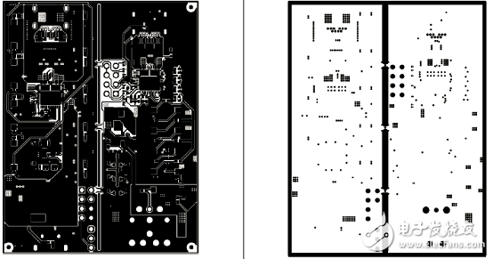
图13.评估板USB-C-PD-DUO-EVM PCB设计图:左:顶层;右:地面1
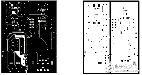
图14.评估板USB-C-PD-DUO-EVM PCB设计图:左:高速;右:地面2
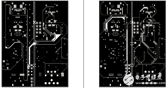
图15.评估板USB-C-PD-DUO-EVM PCB设计图:左:电源1;右:电源2S
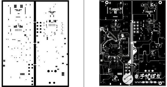
图16.评估板USB-C-PD-DUO-EVM PCB设计图:左:地面3;右:底层
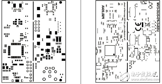
图17.评估板USB-C-PD-DUO-EVM PCB设计图:左:底层焊接;右:底层综合
-
TI 的USB Type-C解决方案2015-08-25 0
-
TI Type-C解决方案22015-08-25 0
-
USB Type-C 和 USB PD 控制器电源开关/高速多路复用器参考设计2018-06-19 0
-
汽车双通道USB Type-C PD DFP车载充电器设计包括BOM及层图2018-10-10 0
-
USB Type-C和USB PD控制器电源开关设计包括BOM及层图2018-10-24 0
-
桶形插孔转USB C PD和USB Type-A转Type-C2018-12-06 0
-
DN05102D 45 W Type-C PD-3.0电源适配器解决方案2019-06-20 0
-
基于TPS55289的USB PD及无线充电解决方案2022-11-03 0
-
Type-C双电池快充的解决方案2022-11-07 0
-
Type-C 双电池快充解决方案2021-08-11 7337
-
Type-C双电池快充解决方案分享2022-01-13 4686
-
Type-C双电池快充解决方案2023-03-22 2970
-
适用于Thunderbolt 3器件且具有集成电源开关的USB Type-C® 和 USB PD控制器TPS65987DDJ数据表2024-03-05 48
-
具有集成电源开关的USB Type-C® 和 USB PD控制器TPS65987DDK数据表2024-03-05 56
-
支持USB3和交替模式的USB Type-C® 和USB PD控制器TPS65987D数据表2024-03-05 51
全部0条评论

快来发表一下你的评论吧 !
