

怎样用Arduino和Wekinator创建传感器控制接口
电子说
描述
输入指令
在这个项目的输入方面,我们需要将MPU6050传感器与Arduino UNO连接。
参考下图,获取有关如何将传感器连接到Arduino的帮助。
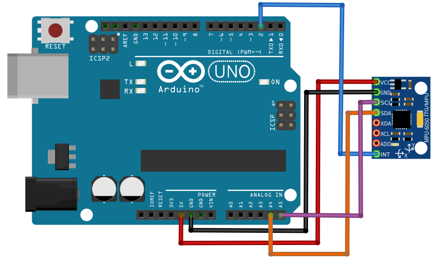
详细说明了MPU6050传感器与Arduino UNO之间的连接。
安装Arduino库
首先,从GitHub下载I2C和MPU6050库,以便与Arduino接口。
解压缩或解压缩下载文件后,导航到Arduino文件夹,复制I2C和MPU6050文件夹并将它们放在Arduino IDE库文件夹中。
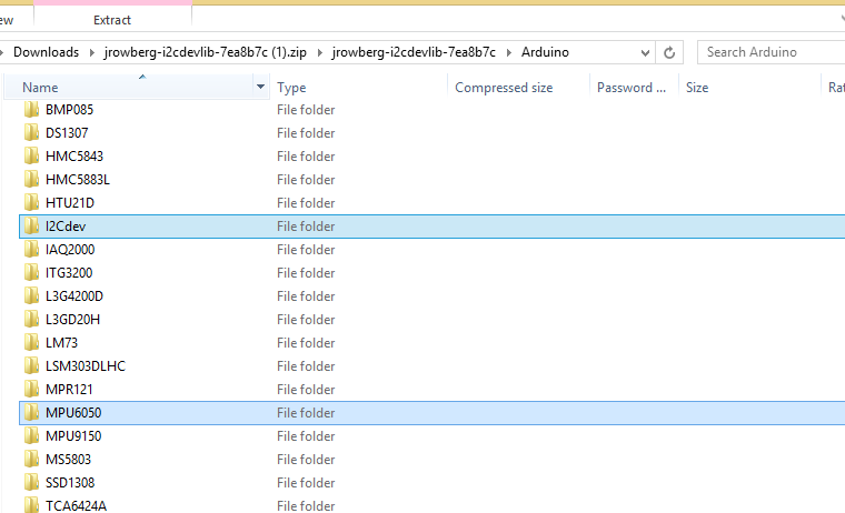
Arduino IDE库文件夹中I2C和MPU6050文件夹的位置。
上传代码流程
撒哈拉title title
启动Arduino IDE。
查找MPU6050文件夹下的示例文件。
打开MPU6050_DMP6文件。
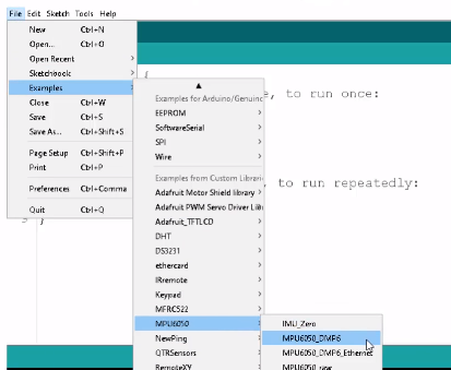
示例下的MPU6050_DMP6文件的位置和MPU6050文件夹。
现在,上传Arduino IDE代码并显示串口监视器。
如果显示输出,那么这表示你‘已成功将传感器与Arduino连接。
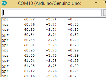
输出数据显示在Arduino中。
要将数据发送到Processing,需要对代码进行一些更改。
首先取消注释117代码行并注释100代码行。
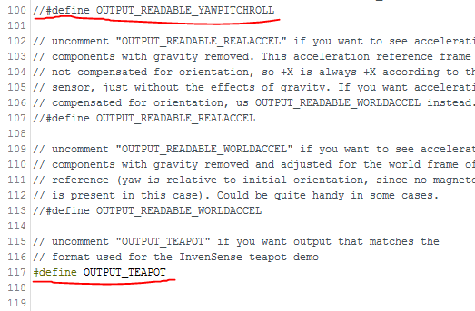
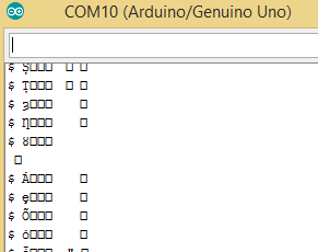
上传代码再次和它笑uld在串口监视器中显示为不可读的字符。
处理代码说明
为了从Arduino接收数据并移动3D模型,需要从bitbucket下载’toxiclibs‘库.org。
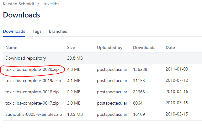
复制zip文件中的所有文件夹并将其粘贴到Processing library文件夹中。
Processing library文件夹可以可在以下位置找到:处理文件夹》模式》 Java》库。
现在,将下面的代码粘贴到Processing然后上传。
代码是MPU6050库中包含的示例的修改版本。
import processing.serial.*;
import processing.opengl.*;
import toxi.geom.*;
import toxi.processing.*;
import oscP5.*;
import netP5.*;
OscP5 oscP5;
NetAddress dest;
ToxiclibsSupport gfx;
Serial port; // The serial port
char[] teapotPacket = new char[14]; // InvenSense Teapot packet
int serialCount = 0; // current packet byte position
int synced = 0;
int interval = 0;
float[] q = new float[4];
Quaternion quat = new Quaternion(1, 0, 0, 0);
float[] gravity = new float[3];
float[] euler = new float[3];
float[] ypr = new float[3];
void setup() {
// 300px square viewport using OpenGL rendering
size(300, 300, OPENGL);
gfx = new ToxiclibsSupport(this);
// setup lights and antialiasing
lights();
smooth();
// display serial port list for debugging/clarity
println(Serial.list());
// get the first available port (use EITHER this OR the specific port code below)
String portName = Serial.list()[0];
// get a specific serial port (use EITHER this OR the first-available code above)
//String portName = “COM4”;
// open the serial port
port = new Serial(this, portName, 115200);
// send single character to trigger DMP init/start
// (expected by MPU6050_DMP6 example Arduino sketch)
port.write(’r‘);
/* start oscP5, sending messages at port 9000 */
oscP5 = new OscP5(this,9000);
dest = new NetAddress(“127.0.0.1”,6448);
}
void draw() {
if (millis() - interval 》 1000) {
// resend single character to trigger DMP init/start
// in case the MPU is halted/reset while applet is running
port.write(’r‘);
interval = millis();
}
// black background
background(0);
// translate everything to the middle of the viewport
pushMatrix();
translate(width / 2, height / 2);
// 3-step rotation from yaw/pitch/roll angles (gimbal lock!)
// 。..and other weirdness I haven’t figured out yet
//rotateY(-ypr[0]);
//rotateZ(-ypr[1]);
//rotateX(-ypr[2]);
// toxiclibs direct angle/axis rotation from quaternion (NO gimbal lock!)
// (axis order [1, 3, 2] and inversion [-1, +1, +1] is a consequence of
// different coordinate system orientation assumptions between Processing
// and InvenSense DMP)
float[] axis = quat.toAxisAngle();
rotate(axis[0], -axis[1], axis[3], axis[2]);
// draw main body in red
fill(255, 0, 0, 200);
box(10, 10, 200);
// draw front-facing tip in blue
fill(0, 0, 255, 200);
pushMatrix();
translate(0, 0, -120);
rotateX(PI/2);
drawCylinder(0, 20, 20, 8);
popMatrix();
// draw wings and tail fin in green
fill(0, 255, 0, 200);
beginShape(TRIANGLES);
vertex(-100, 2, 30); vertex(0, 2, -80); vertex(100, 2, 30); // wing top layer
vertex(-100, -2, 30); vertex(0, -2, -80); vertex(100, -2, 30); // wing bottom layer
vertex(-2, 0, 98); vertex(-2, -30, 98); vertex(-2, 0, 70); // tail left layer
vertex( 2, 0, 98); vertex( 2, -30, 98); vertex( 2, 0, 70); // tail right layer
endShape();
beginShape(QUADS);
vertex(-100, 2, 30); vertex(-100, -2, 30); vertex( 0, -2, -80); vertex( 0, 2, -80);
vertex( 100, 2, 30); vertex( 100, -2, 30); vertex( 0, -2, -80); vertex( 0, 2, -80);
vertex(-100, 2, 30); vertex(-100, -2, 30); vertex(100, -2, 30); vertex(100, 2, 30);
vertex(-2, 0, 98); vertex(2, 0, 98); vertex(2, -30, 98); vertex(-2, -30, 98);
vertex(-2, 0, 98); vertex(2, 0, 98); vertex(2, 0, 70); vertex(-2, 0, 70);
vertex(-2, -30, 98); vertex(2, -30, 98); vertex(2, 0, 70); vertex(-2, 0, 70);
endShape();
popMatrix();
//Send the OSC message
sendOsc();
}
void serialEvent(Serial port) {
interval = millis();
while (port.available() 》 0) {
int ch = port.read();
if (synced == 0 && ch != ‘$’) return; // initial synchronization - also used to resync/realign if needed
synced = 1;
print ((char)ch);
if ((serialCount == 1 && ch != 2)
|| (serialCount == 12 && ch != ‘ ’)
|| (serialCount == 13 && ch != ‘ ’)) {
serialCount = 0;
synced = 0;
return;
}
if (serialCount 》 0 || ch == ‘$’) {
teapotPacket[serialCount++] = (char)ch;
if (serialCount == 14) {
serialCount = 0; // restart packet byte position
// get quaternion from data packet
q[0] = ((teapotPacket[2] 《《 8) | teapotPacket[3]) / 16384.0f;
q[1] = ((teapotPacket[4] 《《 8) | teapotPacket[5]) / 16384.0f;
q[2] = ((teapotPacket[6] 《《 8) | teapotPacket[7]) / 16384.0f;
q[3] = ((teapotPacket[8] 《《 8) | teapotPacket[9]) / 16384.0f;
for (int i = 0; i 《 4; i++) if (q[i] 》= 2) q[i] = -4 + q[i];
// set our toxilibs quaternion to new data
quat.set(q[0], q[1], q[2], q[3]);
// below calculations unnecessary for orientation only using toxilibs
// calculate gravity vector
gravity[0] = 2 * (q[1]*q[3] - q[0]*q[2]);
gravity[1] = 2 * (q[0]*q[1] + q[2]*q[3]);
gravity[2] = q[0]*q[0] - q[1]*q[1] - q[2]*q[2] + q[3]*q[3];
// calculate Euler angles
euler[0] = atan2(2*q[1]*q[2] - 2*q[0]*q[3], 2*q[0]*q[0] + 2*q[1]*q[1] - 1);
euler[1] = -asin(2*q[1]*q[3] + 2*q[0]*q[2]);
euler[2] = atan2(2*q[2]*q[3] - 2*q[0]*q[1], 2*q[0]*q[0] + 2*q[3]*q[3] - 1);
// calculate yaw/pitch/roll angles
ypr[0] = atan2(2*q[1]*q[2] - 2*q[0]*q[3], 2*q[0]*q[0] + 2*q[1]*q[1] - 1);
ypr[1] = atan(gravity[0] / sqrt(gravity[1]*gravity[1] + gravity[2]*gravity[2]));
ypr[2] = atan(gravity[1] / sqrt(gravity[0]*gravity[0] + gravity[2]*gravity[2]));
// output various components for debugging
//println(“q: ” + round(q[0]*100.0f)/100.0f + “ ” + round(q[1]*100.0f)/100.0f + “ ” + round(q[2]*100.0f)/100.0f + “ ” + round(q[3]*100.0f)/100.0f);
//println(“euler: ” + euler[0]*180.0f/PI + “ ” + euler[1]*180.0f/PI + “ ” + euler[2]*180.0f/PI);
println(“ypr: ” + ypr[0]*180.0f/PI + “ ” + ypr[1]*180.0f/PI + “ ” + ypr[2]*180.0f/PI);
}
}
}
}
void drawCylinder(float topRadius, float bottomRadius, float tall, int sides) {
float angle = 0;
float angleIncrement = TWO_PI / sides;
beginShape(QUAD_STRIP);
for (int i = 0; i 《 sides + 1; ++i) {
vertex(topRadius*cos(angle), 0, topRadius*sin(angle));
vertex(bottomRadius*cos(angle), tall, bottomRadius*sin(angle));
angle += angleIncrement;
}
endShape();
// If it is not a cone, draw the circular top cap
if (topRadius != 0) {
angle = 0;
beginShape(TRIANGLE_FAN);
// Center point
vertex(0, 0, 0);
for (int i = 0; i 《 sides + 1; i++) {
vertex(topRadius * cos(angle), 0, topRadius * sin(angle));
angle += angleIncrement;
}
endShape();
}
// If it is not a cone, draw the circular bottom cap
if (bottomRadius != 0) {
angle = 0;
beginShape(TRIANGLE_FAN);
// Center point
vertex(0, tall, 0);
for (int i = 0; i 《 sides + 1; i++) {
vertex(bottomRadius * cos(angle), tall, bottomRadius * sin(angle));
angle += angleIncrement;
}
endShape();
}
}
void sendOsc() {
OscMessage msg = new OscMessage(“/wek/inputs”);
msg.add((float)ypr[2]); // x-axis
msg.add((float)ypr[1]); // y -axis
oscP5.send(msg, dest);
}
上传后代码,窗口应该如下所示。
输出代码指令
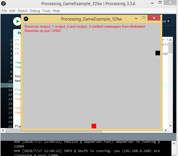
就输出过程而言,一个简单的界面将被设置为从Wekinator接收一个DTW输出。
在界面内,一个方框根据收到的Wekinator输入向左或向右移动。
你可以找到并下载加工草图在Wekinator网站上。
下载‘Simple DTW-controlled-game’文件并在Processing中运行后,它应该如下例所示。
Wekinator说明
启动Wekinator软件并按照以下步骤操作:
设置输入值为2.
将输出值设置为1.
将输出类型保留为默认设置“所有动态时间扭曲”并指定3种手势类型。
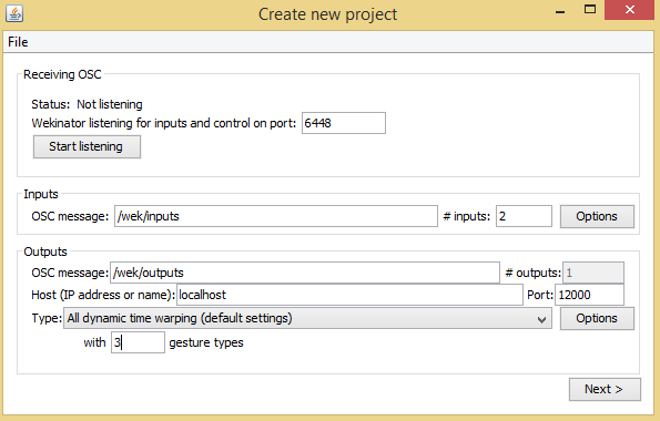
‘创建新项目’窗口,显示Wekinator中的输入,输出和手势类型字段。
单击“下一步”,弹出“新建项目”窗口。
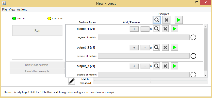
‘新项目’窗口,在Wekinator中包含输出行字段。
然后,单击输出1行上的“加号”按钮并向左倾斜传感器。输出将沿该方向移动框。
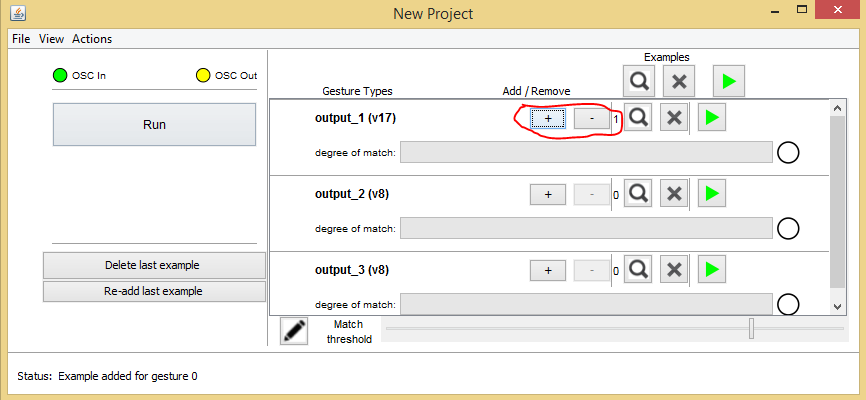
‘新项目’窗口,带有添加/删除按钮。
现在,单击输出2行上的“加号”按钮,然后向右倾斜传感器。输出将相应地移动框。
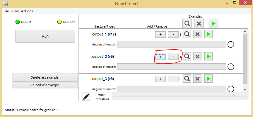
‘New Project’窗口,在Wekinator中用输出2行中的添加/删除按钮。
最后,单击输出3行中的加号按钮并向后倾斜传感器。输出将导致框跳转。
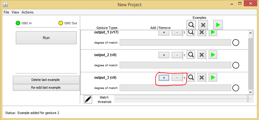
‘New Project’窗口,带有在Wekinator中圈出的添加/删除按钮。

‘新建项目’窗口,输出3行中的添加/删除按钮被圈起来。
录制完成后,根据样本训练Wekinator并运行程序。
然后方框会响应传感器倾斜的方向移动
-
用arduino创建一个游戏控制器2022-11-10 697
-
使用C++创建传感器接口2022-07-18 2903
-
怎样用Arduino和esp8266检测WIFI的信号强度呢2022-02-24 2769
-
怎样用Arduino UNO去测试CCS811气体传感器模块呢2022-01-17 850
-
怎样用CubeMX创建第一个project2021-09-28 1555
-
怎样用单个单相逆变器去监测多个接触式传感器?2021-05-10 1495
-
怎样用Javascript控制Arduino Uno2019-10-22 3491
-
怎样用Wekinator和Arduino控制直流电机2019-08-03 3376
-
怎样用ArduinoUNO创建指纹传感器门锁2019-08-01 7981
-
怎样用Wekinator和Arduino制作颜色分类器2019-07-31 2096
-
怎样将敲击传感器与Arduino接口2019-07-30 11002
-
关于怎样用labview编写加速度传感器程序问题2018-05-15 4210
-
怎样用51单片机控制ky-026火焰传感器模块?2018-04-19 6225
-
怎样用wifi模块控制单片机?那个接口控制单片机的哪个接口2013-05-27 4640
全部0条评论

快来发表一下你的评论吧 !
