

怎样用语音命令控制直流电机
电子说
描述
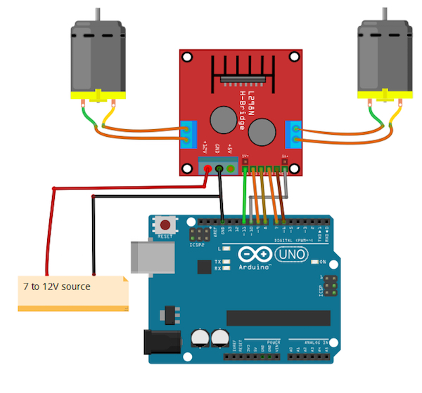
电路图
建立连接如下:
ENA L298N到Arduino 11的引脚
L298N的ENB到Arduino的10号引脚
L298N的IN1到Arduino的9号引脚
L298N的IN2到Arduino的第8针
L298N的IN3到Arduino的第7针
L298N的IN4到Arduino的第6针
将正在使用的电池电源正极连接到L298N的12V连接器,电池到L298N的GND,以及L298N的GND到GND of Arduino
最后,连接L298N两端的两个电机
如何运行程序
首先,在Arduino IDE的帖子末尾复制并粘贴Arduino代码并上传代码。
然后从Wekinator的示例页面下载草图。
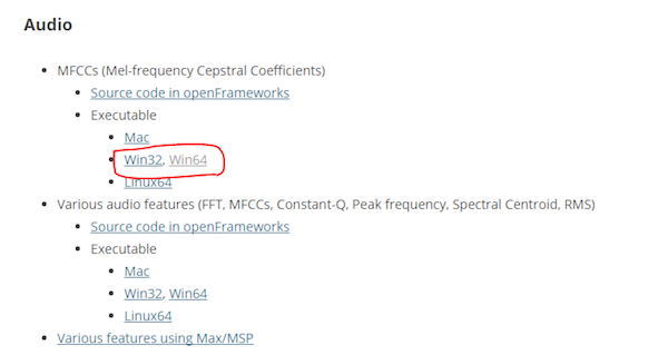
下载MFCC的可执行文件(mel-frequency cepstral coefficient)。我有一个64位操作系统,所以我下载了“win64”。
下载后,将其解压缩并运行“.exe”文件。它将如下所示。现在您需要一个麦克风来为Wekinator提供输入。如果已连接外接麦克风,请确保在声音设置中选择了该麦克风。
您需要另一个草图来获取Wekinator的输出。该草图在本文末尾给出。将其粘贴到新的处理窗口并运行草图。
打开Wekinator并进行如下图所示的设置。将输入设置为13,将输出设置为1.将类型设置为“所有动态时间扭曲”,使用5种手势类型,然后单击“下一步”。
现在按住output_1前面的“+”按钮并说“前进”。
然后按住output_2前面的“+”按钮并说出“向后”。
然后按住output_3前面的“+”按钮并说出“right”。
然后按住output_4前面的“+”按钮并说“左”。
然后按住“ outpu前面的+“按钮t_5并说“停止”。
然后,单击“Train”,然后单击“Run”。确保已上载Arduino代码并且处理草图正在后台运行。现在电机应根据您的声控命令移动。尝试用你的声音进行测试,并在需要时重复上述步骤进行重新训练。
它是如何工作的?
总之,这个项目有三个部分:Wekinator,Processing和Arduino。使用机器学习,Wekinator正在告诉处理它正在收听的语音是否是预先训练好的语音命令。然后处理读取该消息并将其传递给Arduino,然后Arduino决定是否顺时针/逆时针转动电机。 Wekinator和处理之间发生的所有通信都是通过OSC(开放式声音控制)协议。处理和Arduino之间的通信是通过串口完成的。
Arduino代码
#include //Including the library that will help us in receiving and sending the values from processing
ValueReceiver《1》 receiver; /*Creating the receiver that will receive only one value.
Put the number of values to synchronize in the brackets */
/* The below variable will be synchronized in the processing
and it should be same on both sides. */
int output;
//Motor Pins
int EN_A = 11;
int IN1 = 9;
int IN2 = 8;
int IN3 = 7;
int IN4 = 6;
int EN_B = 10;
void setup()
{
/* Starting the serial communication because we are communicating with the
Processing through serial. The baudrate should be same as on the processing side. */
Serial.begin(19200);
//Initializing the motor pins as output
pinMode(EN_A, OUTPUT);
pinMode(IN1, OUTPUT);
pinMode(IN2, OUTPUT);
pinMode(IN3, OUTPUT);
pinMode(IN4, OUTPUT);
pinMode(EN_B, OUTPUT);
digitalWrite(EN_A, HIGH);
digitalWrite(EN_B, HIGH);
// Synchronizing the variable with the processing. The variable must be int type.
receiver.observe(output);
}
void loop()
{
// Receiving the output from the processing.
receiver.sync();
// Matching the received output to light up led‘s
if (output == 1)
{
//Forward
digitalWrite(IN1, LOW);
digitalWrite(IN2, HIGH);
digitalWrite(IN3, LOW);
digitalWrite(IN4, HIGH);
}
else if (output == 2)
{
//Backward
digitalWrite(IN1, HIGH);
digitalWrite(IN2, LOW);
digitalWrite(IN3, HIGH);
digitalWrite(IN4, HIGH);
}
else if (output == 3)
{
//Right
digitalWrite(IN1, LOW);
digitalWrite(IN2, HIGH);
digitalWrite(IN3, LOW);
digitalWrite(IN4, LOW);
}
else if (output == 4)
{
//Left
digitalWrite(IN1, LOW);
digitalWrite(IN2, LOW);
digitalWrite(IN3, HIGH);
digitalWrite(IN4, LOW);
}
else if (output == 5)
{
//Stop
digitalWrite(IN1, LOW);
digitalWrite(IN2, LOW);
digitalWrite(IN3, LOW);
digitalWrite(IN4, LOW);
}
}
处理代码
import vsync.*; // Importing the library that will help us in sending and receiving the values from the Arduino
import processing.serial.*; // Importing the serial library
// Below libraries will connect and send, receive the values from wekinator
import oscP5.*;
import netP5.*;
// Creating the instances
OscP5 oscP5;
NetAddress dest;
ValueSender sender;
// This variable will be syncronized with the Arduino and it should be same on the Arduino side.
public int output;
void setup()
{
// Starting the serial communication, the baudrate and the com port should be same as on the Arduino side.
Serial serial = new Serial(this, “COM10”, 19200);
sender = new ValueSender(this, serial);
// Synchronizing the variable as on the Arduino side.
sender.observe(“output”);
// Starting the communication with wekinator. listen on port 12000, return messages on port 6448
oscP5 = new OscP5(this, 12000);
dest = new NetAddress(“127.0.0.1”, 6448);
}
//This is called automatically when OSC message is received
void oscEvent(OscMessage theOscMessage) {
if (theOscMessage.checkAddrPattern(“/output_1”)==true)
{
output = 1;
}
else if (theOscMessage.checkAddrPattern(“/output_2”)==true)
{
output = 2;
}
else if (theOscMessage.checkAddrPattern(“/output_3”) == true)
{
output = 3;
}
else if (theOscMessage.checkAddrPattern(“/output_4”) == true)
{
output = 4;
}
else if (theOscMessage.checkAddrPattern(“/output_5”) == true)
{
output = 5;
}
else
{
}
}
void draw()
{
// Nothing to be drawn for this example
}
-
直流电机的应用原理及控制原理是什么?2024-10-22 2778
-
直流电机的励磁是直流电吗?直流电机励磁的作用?2024-01-18 5521
-
ros与arduino通信控制直流电机2023-03-31 906
-
直流电机控制的基本方法2023-03-26 9999
-
无刷直流电机和有刷直流电机的区别2023-03-17 10419
-
怎样通过霍尔传感器去控制无刷直流电机呢2021-09-17 4116
-
直流电机控制原理及C程序2021-09-15 1357
-
PWM是怎样去控制stm32直流电机的2021-08-23 1965
-
直流电机PID控制2021-07-26 1666
-
直流电机的控制2021-05-19 1420
-
直流电机控制器的特点_直流电机控制器的弹簧调整要点2020-04-03 3730
-
直流电机PID控制角度2017-05-24 13256
-
直流电机PWM控制2016-11-08 1929
-
直流电机2010-01-09 4477
全部0条评论

快来发表一下你的评论吧 !
