

怎样用声音控制RGBLED的颜色
电子说
描述
连接RGB LED的最长脚到Arduino。通过220欧姆电阻将其他支路连接到Arduino的引脚9,10和11,如下面的电路图所示。

如何运行程序
首先,粘贴在Arduino IDE中本文末尾为Arduino提供的代码并上传代码。
然后,您需要从Wekinator的示例页面下载草图。
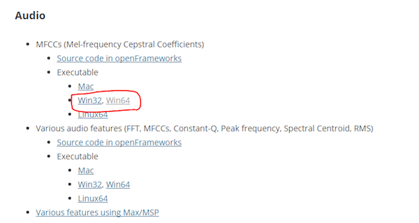
下载MFCC的可执行文件(mel频率倒频谱系数)。我有一个64位操作系统,所以我从那里下载了“win64”。
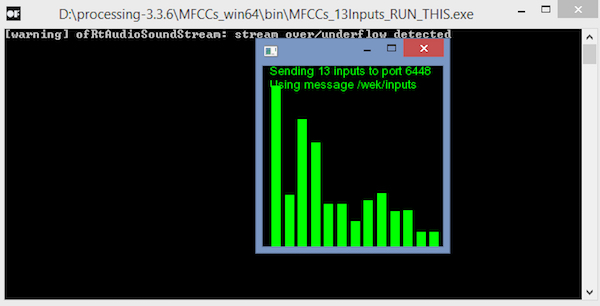
下载后,解压缩并运行“.exe”文件。它将如下所示。现在您需要一个麦克风来为Wekinator提供输入。如果您已连接外接麦克风,请确保在计算机的声音设置中选择它。
您将需要另一个草图(“输出草图”) )从Wekinator获得输出。该草图在本文末尾给出。将其粘贴到新的处理窗口并运行草图。
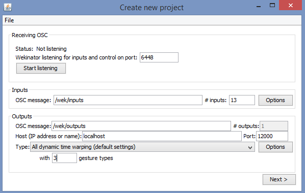
现在打开Wekinator并进行如下图所示的设置。将输入设置为13,将输出设置为1.将类型设置为“所有动态时间扭曲”,使用3种手势类型,然后单击“下一步”。
现在按住output_1前面的“+”按钮并说“红色”。
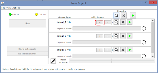
然后按住output_2前面的“+”按钮并说“绿色”。
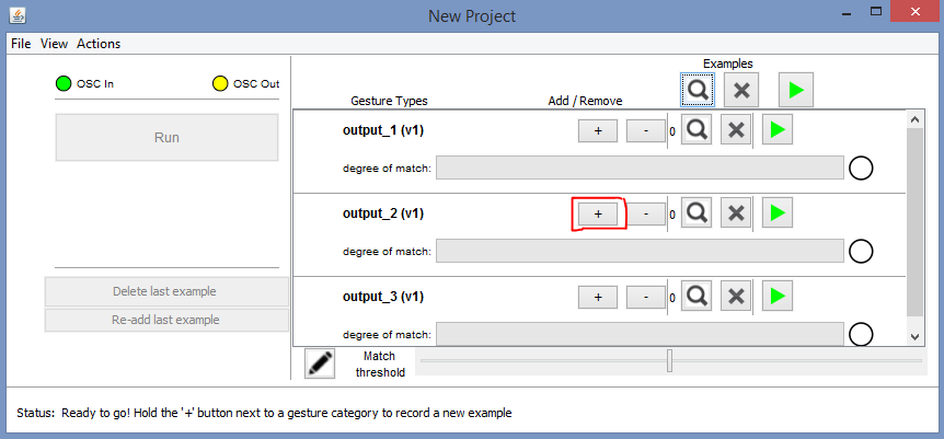
然后按住output_3前面的“+”按钮并说“蓝色”。

之后,单击“Train”,然后单击“Run”。现在,RGB LED的颜色将根据您说的颜色名称而改变。
Arduino代码
#include //Including the library that will help us in receiving and sending the values from processing
ValueReceiver《1》 receiver; /*Creating the receiver that will receive 1 value.
Put the number of values to synchronize in the brackets */
/* The below variable will be synchronized in the processing
and they should be same on both sides. */
int output;
// Initializing the pins for led‘s
int red_light_pin= 11;
int green_light_pin = 10;
int blue_light_pin = 9;
void setup()
{
/* Starting the serial communication because we are communicating with the
Processing through serial. The baudrate should be same as on the processing side. */
Serial.begin(19200);
pinMode(red_light_pin, OUTPUT);
pinMode(green_light_pin, OUTPUT);
pinMode(blue_light_pin, OUTPUT);
// Synchronizing the variable with the processing. The variable must be int type.
receiver.observe(output);
}
void loop()
{
// Receiving the output from the processing.
receiver.sync();
// Matching the received output to light up the RGB LED
if (output == 1)
{
RGB_color(255, 0, 0); // Red
}
else if (output == 2)
{
RGB_color(0, 255, 0); // Green
}
else if (output ==3)
{
RGB_color(0, 0, 255); // Blue
}
}
void RGB_color(int red_light_value, int green_light_value, int blue_light_value)
{
analogWrite(red_light_pin, red_light_value);
analogWrite(green_light_pin, green_light_value);
analogWrite(blue_light_pin, blue_light_value);
}
处理代码(输出草图)
import vsync.*; // Importing the library that will help us in sending and receiving the values from the Arduino
import processing.serial.*; // Importing the serial library
// Below libraries will connect and send, receive the values from wekinator
import oscP5.*;
import netP5.*;
// Creating the instances
OscP5 oscP5;
NetAddress dest;
ValueSender sender;
// This variable will be syncronized with the Arduino and it should be same on the Arduino side.
public int output;
void setup()
{
// Starting the serial communication, the baudrate and the com port should be same as on the Arduino side.
Serial serial = new Serial(this, “COM10”, 19200);
sender = new ValueSender(this, serial);
// Synchronizing the variable as on the Arduino side.
sender.observe(“output”);
// Starting the communication with wekinator. listen on port 12000, return messages on port 6448
oscP5 = new OscP5(this, 12000);
dest = new NetAddress(“127.0.0.1”, 6448);
}
//This is called automatically when OSC message is received
void oscEvent(OscMessage theOscMessage) {
if (theOscMessage.checkAddrPattern(“/output_1”)==true)
{
output = 1;
}
else if (theOscMessage.checkAddrPattern(“/output_2”)==true)
{
output = 2;
}
else if (theOscMessage.checkAddrPattern(“/output_3”) == true)
{
output = 3;
}
else
{
}
}
void draw()
{
// Nothing to be drawn for this example
}
-
已用时间函数怎样用2012-10-08 3766
-
怎样用LABVIEW强度图颜色深浅表示随时间的表变化2013-01-20 9848
-
怎样用FPGA控制舵机2013-10-20 3970
-
怎样用51单片机控制电源2015-07-29 5291
-
labview中怎样用开关控制频率2019-10-17 1869
-
怎样用STM32F407VET6单片机去控制无刷电机呢2021-09-18 2641
-
怎样用ROBO PRO软件去控制慧鱼模型呢2021-09-23 2609
-
怎样用串口通信去控制伺服速度呢2021-10-11 1729
-
怎样用STM32按键去控制LED的亮灭呢2021-10-22 2160
-
请问一下怎样用各种定时器来控制RGB呢2021-11-23 1589
-
请教大神怎样用手机wifi去调LED的颜色呢2022-02-22 1071
-
怎样用万用表判断三极管基极和类型2010-03-06 24289
-
介绍怎样用MCU来生成PWM资料下载2021-04-25 1001
-
怎样用好手中的六位半万用表?2023-03-07 4227
-
PLC中怎样用X和Y两个轴走出直线轨迹?2023-09-12 1938
全部0条评论

快来发表一下你的评论吧 !
