

5v Arduino怎么编程
电子说
描述
第1步:输入命令
这里要看看输入命令。 Arduino上有两种主要类型的引脚,数字I/O(输入/输出)和模拟输入,数字引脚可以是输入和输出,模拟引脚是可以检测电流电压的特殊输入。
PinMode
在我们使用任何传感器或执行器之前,我们需要告诉Arduino它们所在的引脚。
int sensorPin = A1;
Void setup(){
pinMode(sensorPin, INPUT);
}
这告诉Arduino引脚sensorPin上有一个输入,它是一个代表数字A1的整数。我们这样做的原因是因为如果由于某种原因我们需要更改引脚数,我们可以在顶部的一个位置更改它而不是通过整个代码并且每次引用时都必须更改它。这个命令进入Void设置,大多数命令进入Void循环,所以除非另有说明,否则将它们放在那里。
数字读取
这是最基本的输入方式成为Arduino。信号阱为On或Off,用于检测灯开关或按钮的状态。以下是如何使用它。
int DsensorVal = digitalRead(DsensorPin);
这将int DsensorVal指定为与DsensorPin相同的值。在这种情况下,它将是1或0,开或关。
模拟读取
模拟读取命令用于检测Arduino的其中一个模拟引脚上的电压。这用于连接任何发出电压作为数据的传感器,例如光依赖电阻,微调电位器,温度传感器等。
Int AsensorVal = analogRead(AsensorPin);
这将int AsensorVal分配给AsensorPin上的电压。根据0到5伏特之间的电压,这将是介于0和1023之间的值。 1.25v = 256,2.5v = 512,3.25v = 768。
我们将在下一步中看到如何使用这些。
步骤2:如何使用输入值
现在我们有来自传感器的值,可以看看如何使用它们。
IF
是的我说IF,IF命令是最重要的命令。它是我们的执行器和传感器之间的主要桥梁。这是它的使用方式。
if (a == b){
action here(We‘ll discuss this in the next step)
}
括号是我们放置要运行的代码的位置。 ==意味着等于,这必须是两个等于因为只有一个会使a = b并使其始终为真。 ==可以替换以下任何一种,
!=不等于
》大于
》 =大于或等于
《=小于或等于
所以如果a == b那么我们运行括号。我们还可以有多个标准来实现
if ((a == b) && (a 《 c)){
}
现在我们添加了&&&这意味着AND,所以只要a == b AND a
这是最基本和最常用的控制命令。我们可以通过向它添加ELSE来进一步采用此命令。这使得当IF不活动时,ELSE就是。
if (a == b){
{
else{
}
现在当IF为负数时,ELSE括号中的任何内容都会运行。
数字
所以我们使用数字输入的方式是这样的。
If (DsenserVal == 1){
}
1与写入HIGH相同。因此,当DsenserPin上有3-5个伏特时,您设置的动作将会发生。有时按钮设置为反向,因此当按下按钮时它等于0,如果是这样,只需将1更改为0就可以了。
模拟
这就是它变得有趣的地方。
我们有正常的if命令。
if (AsensorVal 《 500){
}
如果IF正在检查AsensorVal的值并对其做出反应,模拟信号更多地用于编辑机器人的响应而不是使其响应。我们还有几个命令来编辑信号,以便最终使用它。
Map
当您需要更改时,map命令很有用某个范围的数字。所以说我有一个300到500之间的int值,我想用它来控制180度的伺服,我可以使用这样的命令
AsensorVal = map(AsensorVal, 300, 500, 0, 180);
现在该值是一个从0到180的数字,它介于300到500之间。所以想想一条200个单位长的线,这会改变它,所以线条长度相同,但现在只有180个单位长。这需要很多复杂的数学,但是Arduino背后的好人已经很容易了。
约束
这个数字必须留在某些界限。所以,如果我这样设置它。
AsensorVal = map(AsensorVal, 0, 180);
它现在只允许AsensorVal在0到180之间,如果它低于0然后它变成0,如果它在上面180它将它改为180,这些数字是它的最小值和最大值。
让我们看看如何在下一步中使用执行器。
步骤3:执行器
因此,您希望了解如何使用执行器,以及正确的步骤。
PinMode
是再次使用PinMode的地方,但是这次使用它来注册OUTPUT。
void setup(){
pinMode(actuatorPin, OUTPUT);
}
现在我们已经宣布ActuatorPin为输出,所以现在我们可以用它作为一个。这是在Void设置中。
myServo.attach
我不打算离开伺服系统,不用担心。伺服系统需要更多设置,但仍然很容易。
#include
Servo myServo; # Makes a servo object
Int servoPin = 9; # The number for this has to one of these pins, 11, 10, 9, 6, 5, 3.
Void setup(){
myServo.attach(servoPin); # Attaching the servo to servoPin, which is equal to 9;
}
首先我们导入伺服库,然后我们将对象设为myServo。然后我们创建一个等于我们想要放置它的引脚的int。这必须是支持在Arduino板上标记的PWM的特殊引脚。然后我们将myServo附加到我们设置的引脚上。将附加命令放在Void设置中。
现在我们进行了这些设置,让我们看看实际的输出信号。
DigitalWrite
这是用于控制LED,Reley以及任何其他开启或关闭的基本开/关输出。
digitalWrite(actuatorPin, HIGH);
现在actuatorPin设置为高,所以任何东西都会开始运行。要关闭它,我们使用。
digitalWrite(actuatorPin, LOW);
AnalogWrite
AnalogWrite命令用于控制电机速度,LED亮度等。大多数Arduinos没有实际的模拟输出,但他们能够模仿它。它们具有特殊引脚,即PWN(脉冲宽度调制),可模拟模拟引脚。我们这样控制它
analogWrite(actuatorPin, Amount);
actuatorPin是执行器所在的销钉。数量可以是0到255之间的数字。
myServo.write
让我们使用一些伺服器。
myServo.write(Val);
首先我们告诉什么伺服,在这种情况下myServo。然后我们说写一个介于0和180之间的值。就像你移动的伺服器一样。
步骤4:调试
它的变化很重要能够调试脚本。这样做的方法是通过与Arduino建立一个串行连接,然后告诉它何时到达某些点。您可以通过进入IDE并按下右上角的按钮并打开放大镜来打开串行监视器。
Serial.begin
第一步是像这样开始我们的串行连接
Serial.begin(9600);
这就是Void设置。这个数字是波特率,暂时保留在9600。
Serial.print
以下是我们在输入中的打印方式
Serial.print(“Hello world”);
Serial.print(AsensorVal);
第一个将Hello World打印到串行监视器中。第二个打印模拟输入的值。
Serial.println
Serial.println与Serial.print相同但它开始一个新行用它。所以,例如。如果我使用Serial.print命令继续打印3,它将收到333333333333.现在,如果我们使用Serial.println打印它,它将收到它
3
3
3
明白了。
第5步:示例
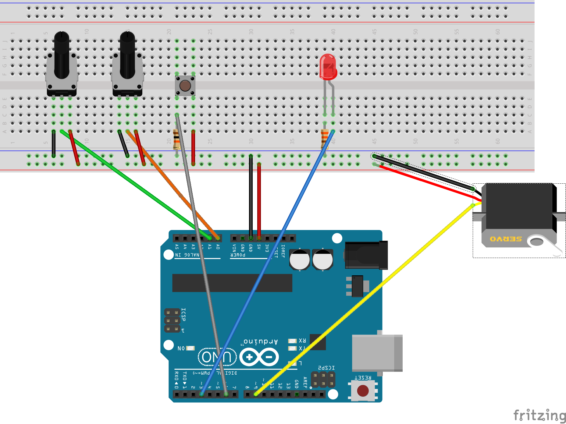
在这里,我将向您展示一个脚本,显示我们学到的一切。如果要构建它,请按照顶部的原理图进行操作。左边的电位器是pot1,控制伺服,右边的电位器是pot2,控制LED的亮度。按钮控制LED是打开还是关闭。
#include
Servo myServo; // Registering our Servo
int servoPin = 9; // The Pin our Servo is on
int lightPin = 3; // The Pin our LED is on
int potPin1 = A1; // The Pin our Potentiometer that controls the Servo is on
int potPin2 = A0; // The Pin our Potentiometer that controls the LED is on
int buttPin = 6; // The Pin our Button is on
void setup(){
myServo.attach(servoPin); // Attaching our servo
pinMode(lightPin, OUTPUT); // Registering our LED Pin as a Output
pinMode(potPin1, INPUT); // Registering our Servo Potentiometer Pin as a Input
pinMode(potPin2, INPUT); // Registering our LED Potentiomerer Pin as a Input
pinMode(buttPin, INPUT); // Registering our Button Pin as a Input
Serial.begin(9600); // Starts the Serial communacation
}
void loop(){
int pot1Val = analogRead(potPin1); // Gets Pot1’s current value
pot1Val = map(pot1Val, 200, 823, 0, 180); // Mapping it so that it removes the beginning and the end of the Pots range
pot1Val = constrain(pot1Val, 0, 180); // Insures that the Servo Input stays between 0 and 180
myServo.write(pot1Val); // Makes the servo move to the current location
Serial.print(“Pot1 value is: ”); // Starts printing in Debug Info
Serial.println(pot1Val); // It‘s now set up so it will say “Pot1 value is: (Current Value)”
int pot2Val = analogRead(potPin2); // Gets Pot2’s current value
pot2Val = map(pot2Val, 0, 1023, 0, 255); // Maps it accordingly
Serial.print(“Pot2 value is: ”); // starts printing in Debug Info
Serial.println(pot2Val); // It will say “Pot2 value is: (Current Value)”
int button = digitalRead(buttPin); // Gets the state of the Button
if(button == 1){ // The way the buttons is set up, 1 means it is being pressed
analogWrite(lightPin, pot2Val); // If its true then turn on the led at this brightness
}
else{ // Else
digitalWrite(lightPin, LOW); // If ELSE is true, which means IF is false, then turn off led
}
delay(50); // Makes a small delay so it isn‘t running every millisecond.
}
步骤6:谢谢
没有进一步的麻烦,我必须告别你再见并感谢您的阅读。我希望这里的信息是有道理的。
- 相关推荐
- 热点推荐
- Arduino
-
EE-39:将5V闪存与ADSP-218x接口(字节编程算法)2025-01-15 302
-
42v转5v 18v转5v 15v转5v稳压降压芯片AH8690概述2023-07-20 3341
-
如何从标准USB插座构建双+5V -5V电源2023-06-29 6121
-
你知道MCU 5V tolerant是什么意思吗2023-05-22 2378
-
基于7805和7905的+5V和-5V电源电路2023-05-13 12304
-
G27 G29变速踏板转USB带ARDUINO PRO MICRO 5V 16MHZ2022-08-17 448
-
电源升压5v芯片归纳2022-01-05 1334
-
5V步进电机马达+ ULN2003驱动板+Arduino2021-08-31 2135
-
EE-39:将5V闪存连接到ADSP-218x(字节编程算法)2021-05-20 647
-
18V转5V,15V转5V的LDO和DC芯片方案2020-11-25 1590
-
3.3V—5V连接技巧与诀窍2015-12-14 1127
-
基于LT1931的+5V~-5V负输出转换器2014-08-07 15073
-
+5V电源2009-10-05 2663
-
-5V电源电路2009-02-21 1372
全部0条评论

快来发表一下你的评论吧 !
