

Arduino颜色选择器的制作
电子说
描述
步骤1:零件清单
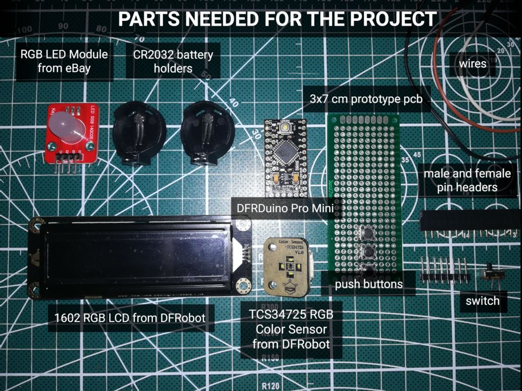
对于此项目,我们需要:
TCS34725 RGB颜色传感器对于Arduino by DFRobot
带有RGB字体显示的I2C 16x2 Arduino LCD DFRobot
DFRobino的DFRduino Pro Mini V1.3(8M3.3V328)
2 x CR2032电池座
滑动开关
RGB LED模块
电线
3x7 cm原型PCB
男性和母针头
2x M2x20螺丝和螺母
工具:
3D打印机,如果你不拥有它,你可以从Shapeways获得印花盒
菲利普斯螺丝刀
烙铁
焊接
步骤2:原理图
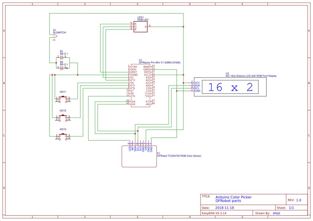
请参阅下面打开视频的装配部分和示意图,了解如何
使用上面提供的原理图进行正确接线。
2》
在测量完零件后,是时候设计一个3D外壳并进行打印了!
设计
以下是我在tinkercad上的设计链接:https://www.tinkercad.com/things/dG47Pr28uwx
上面的内容设计非常适合上面列出的所有组件。
前部将固定LCD屏幕和颜色传感器。
主要的3x7 cm PCB将容纳DFRDuino Pro Mini,电池座和3个按钮,将是从内部拧到后部。
RGB LED将位于后部顶部内部。
电源开关将安装在后部的小孔中。
打印
准备打印的3D模型是av适用于Thingiverse:https://www.thingiverse.com/thing:3223709
打印设置可能因打印机而异。
电池盖部件和前部需要支撑因为前部有一个内置的距离,可以提供颜色传感器和样品之间的距离。
如果你没有3D打印机,你可以从Shapeways获得印刷品:点击这里
汇编
有关汇编说明,请参阅开头提供的视频的汇编部分。
第4步:源代码
GitHub上免费提供源代码:https://github.com/alojzjakob/Arduino-Color-Picker
非常欢迎您改进代码,因为提供的代码只是起点,但效果很好。
这个项目使用这两个特定的库,所以一定要把它们添加到你的Arduino IDE中:
https://github.com/bearwaterfall/DFRobot_LCD-master/tree/master
https://github.com/DFRobot/DFRobot_TCS34725/raw/master/DFRobot_TCS34725.rar
#include
#include
#define ledPin 12
#define redpin 3
#define greenpin 5
#define bluepin 6
const int8_t button1Pin = 7; //1
const int8_t button2Pin = 8; //2
const int8_t button3Pin = 9; //3
int8_t button1State = 0;
int8_t button2State = 0;
int8_t button3State = 0;
#define ACTIVATED LOW
// for a common anode LED, connect the common pin to +5V
// for common cathode, connect the common to ground
// set to false if using a common cathode LED
#define commonAnode true
// our RGB -》 eye-recognized gamma color
byte gammatable[256];
DFRobot_LCD lcd(16,2);
DFRobot_TCS34725 tcs = DFRobot_TCS34725(0x50, TCS34725_GAIN_60X);
bool ledEnabled=false;
int lightsMode=0;
// make some custom characters:
byte light_on[8] = {
0b00100,
0b00100,
0b01110,
0b11111,
0b11111,
0b01110,
0b00000,
0b10101
};
byte light_off[8] = {
0b00100,
0b00100,
0b01110,
0b10001,
0b10001,
0b01110,
0b00000,
0b00000
};
byte rgb_on[8] = {
0b00000,
0b10101,
0b00000,
0b01110,
0b01110,
0b01110,
0b11111,
0b11111
};
byte rgb_off[8] = {
0b00000,
0b00000,
0b00000,
0b01110,
0b01010,
0b01010,
0b10001,
0b11111
};
void setup() {
lcd.init();
// create a new character
lcd.customSymbol(0, light_on);
lcd.customSymbol(1, light_off);
lcd.customSymbol(2, rgb_on);
lcd.customSymbol(3, rgb_off);
pinMode(ledPin, OUTPUT);
digitalWrite(ledPin, LOW);
pinMode(button1Pin, INPUT);
pinMode(button2Pin, INPUT);
pinMode(button3Pin, INPUT);
digitalWrite(button1Pin, HIGH);
digitalWrite(button2Pin, HIGH);
digitalWrite(button3Pin, HIGH);
pinMode(redpin, OUTPUT);
pinMode(greenpin, OUTPUT);
pinMode(bluepin, OUTPUT);
analogWrite(redpin,0);
analogWrite(greenpin,0);
analogWrite(bluepin,0);
// thanks PhilB for this gamma table! it helps convert RGB colors to what humans see
for (int i=0; i《256; i++) {
float x = i;
x /= 255;
x = pow(x, 2.5);
x *= 255;
if (commonAnode) {
gammatable[i] = 255 - x;
} else {
gammatable[i] = x;
}
}
}
void loop() {
button1State = digitalRead(button1Pin);
button2State = digitalRead(button2Pin);
button3State = digitalRead(button3Pin);
int btn=0;
if(button1State==LOW){
btn=1;
}
if(button2State==LOW){
btn=2;
}
if(button3State==LOW){
btn=3;
lightsMode++;
if(lightsMode==4){
lightsMode=0;
}
}
uint16_t clear, red, green, blue;
tcs.getRGBC(&red, &green, &blue, &clear);
// Figure out some basic hex code for visualization
uint32_t sum = clear;
float r, g, b;
r = red; r /= sum;
g = green; g /= sum;
b = blue; b /= sum;
r *= 255; g *= 255; b *= 255;
String redHex,greenHex,blueHex;
redHex = String((int)r, HEX);
greenHex = String((int)g, HEX);
blueHex = String((int)b, HEX);
lcd.setRGB(r,g,b); //Set lcd backlight RGB Value
lcd.setCursor(0,0); // print values on lcd
lcd.print(“#”); lcd.print(redHex); lcd.print(greenHex); lcd.print(blueHex); lcd.print(“ ”);
lcd.setCursor(0,1);
lcd.print(“rgb(”);
lcd.print((int)r); lcd.print(“,”);
lcd.print((int)g); lcd.print(“,”);
lcd.print((int)b); lcd.print(“) ”);
if(lightsMode==0){
ledEnabled=false;
lcd.setCursor(15,0);
lcd.write((unsigned char)1);//light off
lcd.setCursor(14,0);
lcd.write((unsigned char)2);//rgb led on
//Set the color of RGB led indicator
analogWrite(redpin, round(gammatable[(int)r]/4));
analogWrite(greenpin, round(gammatable[(int)g]/4));
analogWrite(bluepin, round(gammatable[(int)b]/4));
}
if(lightsMode==1){
ledEnabled=true;
lcd.setCursor(15,0);
lcd.write((unsigned char)0);//light on
lcd.setCursor(14,0);
lcd.write((unsigned char)2);//rgb led on
//Set the color of RGB led indicator
analogWrite(redpin, round(gammatable[(int)r]/4));
analogWrite(greenpin, round(gammatable[(int)g]/4));
analogWrite(bluepin, round(gammatable[(int)b]/4));
}
if(lightsMode==2){
ledEnabled=true;
lcd.setCursor(15,0);
lcd.write((unsigned char)0);//light on
lcd.setCursor(14,0);
lcd.write((unsigned char)3);//rgb led off
//Set the color of RGB led indicator
analogWrite(redpin, 255);
analogWrite(greenpin, 255);
analogWrite(bluepin, 255);
}
if(lightsMode==3){
ledEnabled=false;
lcd.setCursor(15,0);
lcd.write((unsigned char)1);//light off
lcd.setCursor(14,0);
lcd.write((unsigned char)3);//rgb led off
//Set the color of RGB led indicator
analogWrite(redpin, 255);
analogWrite(greenpin, 255);
analogWrite(bluepin, 255);
}
if(ledEnabled){
digitalWrite(ledPin, HIGH);
}else{
digitalWrite(ledPin, LOW);
}
//delay(10);
}
第5步:享受您的新工具+改进计划
现在你可以到处选择一些漂亮的颜色:)
- 相关推荐
- 热点推荐
- Arduino
-
如何使用Arduino制作随机选项选择器2022-11-03 901
-
如何为Arduino led项目选择颜色2022-10-27 560
-
TTGO颜色选择器2022-07-06 1023
-
TTGO颜色选择器资料分享2022-07-01 2309
-
高度可定制的颜色选择器2022-03-28 589
-
什么是选择器 CSS选择器有哪些2021-07-31 8386
-
jquery隐藏显示元素 jQuery中选择器的种类2021-07-30 2306
-
颜色选择器如何自定义颜色2020-06-03 1057
-
颜色选择器手动输入RGB值关闭窗口时插入的值会改变2019-10-21 2224
-
多路选择器有哪些_多路选择器分类介绍2018-04-27 38515
-
多重布尔按钮选择器2017-03-06 2799
-
labview颜色选择器2016-04-25 30097
-
数据选择器2009-03-28 4373
全部0条评论

快来发表一下你的评论吧 !
