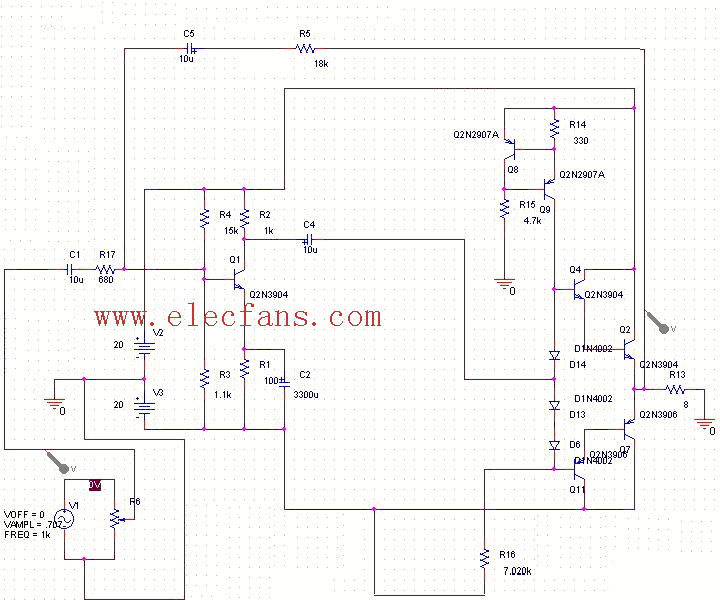

甲类分立元件功率放大器电路图
功率放大器电路图
描述
甲类分立元件功率放大器电路图15W

此功率放大器电路是使用双20V电压电源,提供15W的不失真功率在8欧姆负载的时候。Q1 经营在共同的放射器, 输入信号通过对偏压管子包括Q8, Q9 、D6 、D13 和D14 。Q8 和Q9 提供恒流偏压, 产品阶段减到最小由分离darlington 对(Q2,q4) 形成并且(Q7, q11) 。前二支晶体管是力量Transitors, 具体地2N3055 和MJ2955 。7.02K 电阻器, R16 被做了使用4.7K 、680 欧姆, 和二820 欧姆的系列组合。1.1K 电阻器, R3 被做了使用一100 欧姆和1K 电阻器。没什么问题吧,好理解吧.
This amplifier uses a dual 20 Volt power supply and delivers 15 watts RMS into an 8 ohm load. Q1 operates in common emitter, the input signal being passed to the bias chain consisting of Q8, Q9, D6, D13 and D14. Q8 and Q9 provide a constant current through the bias chain to minimize distortion, the output stage formed by a discrete darlington pair (Q2,Q4) and (Q7,Q11). The last two transistors are power Transitors, specifically the 2N3055 and MJ2955. The 7.02K resistor, R16 was made using a series combination of a 4.7K, 680 Ohms, and two 820 Ohms. The 1.1K resistor, R3 was made using a 100 Ohms and a 1K resistor. You can use this circuit with any walkman or CD player since it is designed to take a standard 500mv RMS signal.are you understand.
-
甲类功率放大器基本电路图2009-05-06 14018
-
请问有分立元件功率放大器原理图吗?2019-11-11 0
-
功率放大器的设计资料分享2021-11-11 0
-
开关功率放大器电路图2009-03-20 2563
-
反相功率放大器电路图2009-03-23 2034
-
相同功率放大器电路图2009-03-23 911
-
宽带功率放大器电路图2009-07-13 1777
-
设计的功率放大器电路图2009-08-13 1184
-
分立元件功率放大器原理图2009-09-10 5504
-
集成功率放大器件或分立元件放大电路的比较2009-09-17 8863
-
分立元件50W高保真功率放大器制作电路图2011-11-11 15767
-
甲类功率放大器电路、特点及功率计算2017-01-18 37967
-
自制分立元件50W高保真功率放大器电路图2021-05-27 3634
-
纯甲类功率放大器的制作(中)2021-06-09 1220
-
MOS管功率放大器电路图与原理图文及其解析2023-02-16 1153
全部0条评论

快来发表一下你的评论吧 !

