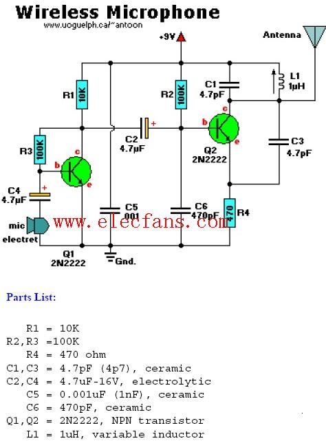

无线话筒电路图
无线通信电子电路图
69人已加入
描述
Couple Notes:
Q1 amplifies input signal via C4 from the electret microphone.
Q2 acts as an oscillator and the signal coming off C2 is fed onto the base of Q2.
L1/C1 is a called 'tank' circuit in the 88MHZ band on your regular AM/FM radio dial.L1 is a 1uH variable inductor ciol be able to tune it a little bit,and the range of 1uH is approximate.
The antenna can be as simple as a 8 "(21cm)piece of wire of and king.

声明:本文内容及配图由入驻作者撰写或者入驻合作网站授权转载。文章观点仅代表作者本人,不代表电子发烧友网立场。文章及其配图仅供工程师学习之用,如有内容侵权或者其他违规问题,请联系本站处理。
举报投诉
-
简易调频无线话筒电路图2019-02-07 18413
-
9018无线话筒电路图(四款无线话筒电路图)2018-01-25 38605
-
调频无线话筒的电路图2016-01-15 1697
-
增强型无线话筒电路图2011-12-21 7050
-
简易无线话筒电路图2010-08-25 3755
-
3V微型无线话筒电路图2009-11-18 3857
-
无线话筒的电路图2009-07-30 2460
-
能消除声反馈的无线话筒电路图2009-07-29 1161
-
调幅式无线话筒电路图2009-04-14 2707
-
无线话筒电路图2008-08-26 6705
-
无线话筒电路图大全2007-12-07 7991
全部0条评论

快来发表一下你的评论吧 !

