
使用Arduino的简易智能机器人手臂的制作
电子说
描述
第1步:你需要的东西: -
以下列出了您需要的东西: -
1。伺服电机x 5
美国链接: - https://amzn.to/2OxbSH7
欧洲链接: - https://amzn.to/2Ddr6Pw
2。电位计x 5(我使用过100k。)
美国链接: - https://amzn.to/2ROjhDM
欧洲链接: - https://amzn.to/2AYlhE7
3。 Arduino UNO。 (您也可以使用Arduino Nano)
美国链接: - https://amzn.to/2DBbENW
欧洲链接: - https://amzn.to/2zHCQX7
4 。面包板。 (我建议使用此套件)
美国链接: - https://amzn.to/2Dy86w4
欧洲链接: - https://amzn.to/2AZa5ao
5。电池。 (可选,我使用的是5v适配器)
6。纸板/木板/太阳板/丙烯板可用或易于找到。
您还需要安装Arduino IDE。
步骤2:制作手臂: -
在这里,我使用冰棍棒制作手臂。您可以使用任何可用的物资。你可以尝试不同的机械设计,以制造更好的手臂。我的设计不是很稳定。
我只是用双面胶带将舵机粘在冰棒上并用螺丝固定。
对于Master臂我将电位器粘在冰棒上棍棒和手臂。
参考图片会给你一个更好的主意。
我已将所有东西安装在用作基础的A4尺寸帆布板上。
步骤3:建立连接: -


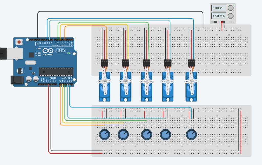
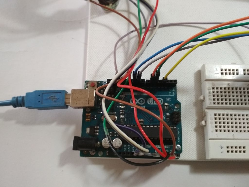
在此步骤中,我们将进行所有必要的连接,请参阅上面的图片。
首先连接所有伺服器与电源并联(红线至+ ve和黑线或棕线至Gnd)
然后将信号线(即黄线或橙线)连接到arduino的PWM引脚。
现在将电位器并联连接到+ 5v和arduino的Gnd。
将中间端子连接到ardunio的模拟引脚。
此处数字引脚3,5,6,9和10用于控制伺服电压
模拟引脚A0至A4用于电位计输入。
连接到引脚3的伺服将由连接到A0的电位器控制
连接到引脚5的伺服将由A1上的电位器控制,依此类推。..。
注意: - 即使Servos不是由arduino供电,也要确保将伺服器的Gnd连接到arduino,否则手臂将无法正常工作。
步骤4:编码: -

此代码的逻辑非常简单,电位计的值存储在数组中,然后使用for循环遍历记录,伺服器按照步骤执行步骤价值。您可以查看本教程,我用作参考“Arduino电位器伺服控制和记忆”
代码: - (可下载文件附后)。
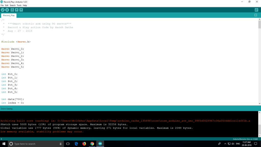
首先我们将声明所有全局必要的变量,因此我们可以在整个程序中使用它们。此处不需要特别说明。
#include
//Servo Objects
Servo Servo_0;
Servo Servo_1;
Servo Servo_2;
Servo Servo_3;
Servo Servo_4;
//Potentiometer Objects
int Pot_0;
int Pot_1;
int Pot_2;
int Pot_3;
int Pot_4;
//Variable to store Servo Position
int Servo_0_Pos;
int Servo_1_Pos;
int Servo_2_Pos;
int Servo_3_Pos;
int Servo_4_Pos;
//Variable to store Previous position values
int Prev_0_Pos;
int Prev_1_Pos;
int Prev_2_Pos;
int Prev_3_Pos;
int Prev_4_Pos;
//Variable to store Current position values
int Current_0_Pos;
int Current_1_Pos;
int Current_2_Pos;
int Current_3_Pos;
int Current_4_Pos;
int Servo_Position; //Stores the angle
int Servo_Number; //Stores no of servo
int Storage[600]; //Array to store data (Increasing array size will consume more memory)
int Index = 0; // Array index starts from 0th position
char data = 0; //variable to store data from serial input.
现在我们将编写一个设置功能,我们设置引脚及其功能。这是首先执行的主要功能。
void setup()
{
Serial.begin(9600); //For Serial communication between arduino and IDE.
//Servo objects are attached to PWM pins.
Servo_0.attach(3);
Servo_1.attach(5);
Servo_2.attach(6);
Servo_3.attach(9);
Servo_4.attach(10);
//Servos are set to 100 position at initialization.
Servo_0.write(100);
Servo_1.write(100);
Servo_2.write(100);
Servo_3.write(100);
Servo_4.write(100);
Serial.println(“Press ‘R’ to Record and ‘P’ to play”);
}
现在我们必须使用模拟输入引脚读取电位计的值并将它们映射到控制伺服系统。为此我们将定义一个函数并将其命名为 Map_Pot(); ,你可以将它命名为任何你想要的用户定义函数。
void Map_Pot()
{
/* The servos rotate at 180 degrees
but to using it to limits is not
a good idea as it makes the servos buzz continuously
which is annoying so we limit the servo to move
between: 1-179 */
Pot_0 = analogRead(A0); // Read input from pot and store it in the Variable Pot_0.
Servo_0_Pos = map(Pot_0, 0, 1023, 1, 179); //Map servos as per the value between 0 to 1023
Servo_0.write(Servo_0_Pos); //Move the servo to that position.
Pot_1 = analogRead(A1);
Servo_1_Pos = map(Pot_1, 0, 1023, 1, 179);
Servo_1.write(Servo_1_Pos);
Pot_2 = analogRead(A2);
Servo_2_Pos = map(Pot_2, 0, 1023, 1, 179);
Servo_2.write(Servo_2_Pos);
Pot_3 = analogRead(A3);
Servo_3_Pos = map(Pot_3, 0, 1023, 1, 179);
Servo_3.write(Servo_3_Pos);
Pot_4 = analogRead(A4);
Servo_4_Pos = map(Pot_4, 0, 1023 , 1, 179);
Servo_4.write(Servo_4_Pos);
}
现在我们将编写循环函数:
void loop()
{
Map_Pot(); //Function call to read pot values
while (Serial.available() 》 0)
{
data = Serial.read();
if (data == ‘R’)
Serial.println(“Recording Moves.。.”);
if (data == ‘P’)
Serial.println(“Playing Recorded Moves.。.”);
}
if (data == ‘R’) //If ‘R’ is entered, start recording.
{
//Store the values in a variable
Prev_0_Pos = Servo_0_Pos;
Prev_1_Pos = Servo_1_Pos;
Prev_2_Pos = Servo_2_Pos;
Prev_3_Pos = Servo_3_Pos;
Prev_4_Pos = Servo_4_Pos;
Map_Pot(); // Map function recalled for comparison
if (abs(Prev_0_Pos == Servo_0_Pos)) // absolute value is obtained by comparing
{
Servo_0.write(Servo_0_Pos); // If values match servo is repositioned
if (Current_0_Pos != Servo_0_Pos) // If values don‘t match
{
Storage[Index] = Servo_0_Pos + 0; // Value is added to array
Index++; // Index value incremented by 1
}
Current_0_Pos = Servo_0_Pos;
}
/* Similarly the value comparison is done for all the servos, +100 is added every for entry
as a differential value. */
if (abs(Prev_1_Pos == Servo_1_Pos))
{
Servo_1.write(Servo_1_Pos);
if (Current_1_Pos != Servo_1_Pos)
{
Storage[Index] = Servo_1_Pos + 100;
Index++;
}
Current_1_Pos = Servo_1_Pos;
}
if (abs(Prev_2_Pos == Servo_2_Pos))
{
Servo_2.write(Servo_2_Pos);
if (Current_2_Pos != Servo_2_Pos)
{
Storage[Index] = Servo_2_Pos + 200;
Index++;
}
Current_2_Pos = Servo_2_Pos;
}
if (abs(Prev_3_Pos == Servo_3_Pos))
{
Servo_3.write(Servo_3_Pos);
if (Current_3_Pos != Servo_3_Pos)
{
Storage[Index] = Servo_3_Pos + 300;
Index++;
}
Current_3_Pos = Servo_3_Pos;
}
if (abs(Prev_4_Pos == Servo_4_Pos))
{
Servo_4.write(Servo_4_Pos);
if (Current_4_Pos != Servo_4_Pos)
{
Storage[Index] = Servo_4_Pos + 400;
Index++;
}
Current_4_Pos = Servo_4_Pos;
}
/* Values are printed on serial monitor, ’ ‘ is for displaying values in tabular format */
Serial.print(Servo_0_Pos);
Serial.print(“ ”);
Serial.print(Servo_1_Pos);
Serial.print(“ ”);
Serial.print(Servo_2_Pos);
Serial.print(“ ”);
Serial.print(Servo_3_Pos);
Serial.print(“ ”);
Serial.println(Servo_4_Pos);
Serial.print (“Index = ”);
Serial.println(Index);
delay(50);
}
if (data == ’P‘) //IF ’P‘ is entered , Start playing recorded moves.
{
for (int i = 0; i 《 Index; i++) //Traverse the array using for loop
{
Servo_Number = Storage[i] / 100; // Finds number of servo
Servo_Position = Storage[i] % 100; // Finds position of servo
switch(Servo_Number)
{
case 0:
Servo_0.write(Servo_Position);
break;
case 1:
Servo_1.write(Servo_Position);
break;
case 2:
Servo_2.write(Servo_Position);
break;
case 3:
Servo_3.write(Servo_Position);
break;
case 4:
Servo_4.write(Servo_Position);
break;
}
delay(50);
}
}
}
代码准备好后,立即将其上传到arduino板。
Smart arm已准备就绪。这个功能还不如Stoerpeak制作的那么顺畅。
如果您可以更好地编写代码或对我有任何建议,请在评论部分告诉我。
有人说过,让我们继续测试。..。
步骤5:测试: -
将代码成功上传到电路板后,打开“串行监视器”,您可以在“工具”选项中找到它。当串行监视器启动时,arduino将重置。现在,您可以使用主臂控制机械臂。但没有记录任何东西。
要开始录制,请在显示器中输入“R”,然后您可以执行要录制的移动。
移动完成后,您必须输入“P”才能播放录制的动作。只要电路板未复位,伺服器就会继续执行移动。
责任编辑:wv
-
如何创建FPGA控制的机器人手臂2023-10-24 2188
-
用于Arduino Due的DIY Braccio机器人手臂护罩2023-06-14 1101
-
Arduino机器人手臂2022-12-30 714
-
构建可帮助人们做早餐的桌面智能机器人手臂2022-12-28 613
-
机器人手臂使用哪种型号的泰和承比较合适2022-03-17 944
-
中国科大展示软体机器人手臂在日常生活中的巨大应用潜力2021-04-13 3725
-
Arduino与树莓派打造Chatbot语音控制机器人手臂2021-03-16 1248
-
Hibot机器人手臂Float Arm可用于哪些应用环境2020-04-20 6529
-
在未来机器人手臂将可以替代人类的双手2019-09-17 2357
-
关于智能机器人手臂机械结构和接线分析制作2019-08-22 9087
-
怎样使用Android手机的蓝牙控制机器人手臂2019-07-29 9316
-
机器人手臂的典型机构有哪些2019-07-08 81997
-
机器人手臂5种不同的运动组合2018-04-18 19426
全部0条评论

快来发表一下你的评论吧 !

