
如何使用ESP模块构建自己的WiFi交换机以及如何控制任何设备
电子说
描述
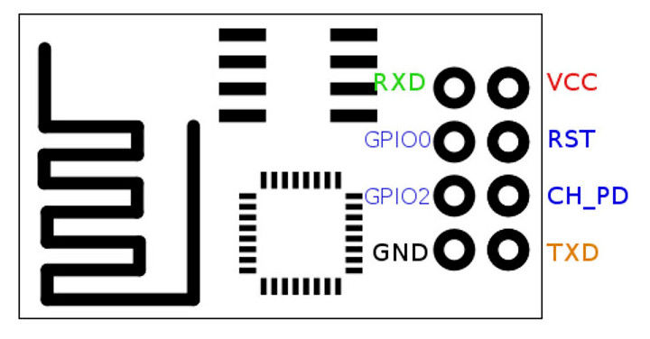
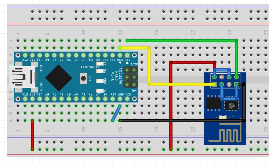
步骤1:原理图:
您可以使用PCBGoGo制造PCB。/p》
步骤2:Ubidots设备和变量创建。
a。转到您的Ubidots帐户的“设备”部分,然后创建一个名为“ wifiswitch”的新设备。
b。在您的“ wifiswitch”设备内,创建一个名为“ light”的变量。
步骤3:Ubidots仪表盘和小部件创建。
一个。创建设备和变量后,我们可以创建仪表板和小部件以控制来自Web或移动仪表板的灯光。要创建新的仪表板,请按“数据》仪表板”。然后按加号图标,然后根据需要完成仪表板配置。
b。现在,创建一个控件小部件以设置与变量“ light”关联的灯泡的状态。要创建控件小部件,请选择页面右上方的加号图标。然后按“切换”作为窗口小部件类型,选择所需的变量进行控制,并根据需要完成窗口小部件的配置。
c。然后即可开始编程和测试项目。
步骤4:使用Arduino IDE进行编程。
1。如果尚未完成,请下载Arduino IDE。
1a上。打开Arduino IDE,然后选择文件-》首选项
1b。将以下网址添加到“其他董事会经理网址”字段中。您可以使用逗号分隔多个URL。
http://arduino.esp8266.com/stable/package_esp8266.。.
2。在Boards Manager中打开并安装ESP8266板:工具-》 Board-》 Boards Manager
2a。您可以通过在搜索栏中键入“ ESP8266”来轻松找到该板。
3。现在,从工具-》板菜单中选择通用ESP8266板
4。定义或仔细检查设备正在与之通信的PC的端口。转到工具-》端口:-》选择端口。
4b。通过转到工具-》上传速度-》 115200
5,确保您的IDE上传速度为115200。如果尚未下载UbidotsESPMQTT库,请下载它。现在,单击Sketch –》 Include Library –》 Add .ZIP Library并选择Ubidots ESP8266 MQTT库。
如果上传正确,您将得到响应:“库已添加到库中。”
8。关闭并再次打开Arduino IDE。
步骤5:编程ESP8266:


设置好ESP8266之后,我们就可以开始从Ubidots发布数据和向Ubidots订购数据,以控制Wifi开关。
1.将以下代码复制并粘贴到Arduino IDE中。不要忘记自定义Wi-Fi SSID和密码以及您的Ubidots令牌。
2。在此处下载代码:
/****************************************
* Libraries
****************************************/
#include “UbidotsESPMQTT.h”
/****************************************
* Define constants
****************************************/
#define TOKEN “。..。..。..。..。..。..。..。..。..” // Your Ubidots TOKEN
#define WIFINAME “。..。..。..” //Your SSID
#define WIFIPASS “。..。..。..” // Your Wifi Pass
#define DEVICE_LABEL “wifiswitch” // Name of the device
#define VARIABLE_LABEL1 “light” // Name of the Ubidots variable
const int ERROR_VALUE = 65535; // Error value
const uint8_t NUMBER_OF_VARIABLES = 2; // Cantidad de variables a las que el programa se va a suscribir
char * variable_labels[NUMBER_OF_VARIABLES] = {“light”}; // Variables names
#define luz 0
#define boton 2
int seguro=0;
int ledState = LOW; // the current state of the output pin
int buttonState; // the current reading from the input pin
int lastButtonState = HIGH; // the previous reading from the input pin
int reading;
unsigned long lastDebounceTime = 0; // the last time the output pin was toggled
unsigned long debounceDelay = 50;
float estadoluz; // Variable to be used in the code
float value; // Variable to store input data
uint8_t variable; // To use with the switch case
Ubidots ubiClient(TOKEN);
WiFiClient client;
/****************************************
* Auxiliar functions
****************************************/
void callback(char* topic, byte* payload, unsigned int length) {
char* variable_label = (char *) malloc(sizeof(char) * 30);
get_variable_label_topic(topic, variable_label);
value = btof(payload, length);
set_state(variable_label);
execute_cases();
free(variable_label);
/////////////////Light////////////////////
digitalWrite(luz, estadoluz);
/////////////////Light////////////////////
}
// Parse topic to extract the variable label which changed value
void get_variable_label_topic(char * topic, char * variable_label) {
Serial.print(“topic:”);
Serial.println(topic);
sprintf(variable_label, “”);
for (int i = 0; i 《 NUMBER_OF_VARIABLES; i++) {
char * result_lv = strstr(topic, variable_labels[i]);
if (result_lv != NULL) {
uint8_t len = strlen(result_lv);
char result[100];
uint8_t i = 0;
for (i = 0; i 《 len - 3; i++) {
result[i] = result_lv[i];
}
result[i] = ‘’;
Serial.print(“Label is: ”);
Serial.println(result);
sprintf(variable_label, “%s”, result);
break;
}
}
}
// cast from an array of chars to float value.
float btof(byte * payload, unsigned int length) {
char * demo = (char *) malloc(sizeof(char) * 10);
for (int i = 0; i 《 length; i++) {
demo[i] = payload[i];
}
float value = atof(demo);
free(demo);
return value;
}
// State machine to use switch case
void set_state(char* variable_label) {
variable = 0;
for (uint8_t i = 0; i 《 NUMBER_OF_VARIABLES; i++) {
if (strcmp(variable_label, variable_labels[i]) == 0) {
break;
}
variable++;
}
if (variable 》= NUMBER_OF_VARIABLES) variable = ERROR_VALUE; // Not valid
}
// Function with switch case to determine which variable changed and assigned the value accordingly to the code variable
void execute_cases() {
switch (variable) {
case 0:
estadoluz = value;
Serial.print(“Luz: ”);
Serial.println(estadoluz);
Serial.println();
break;
case ERROR_VALUE:
Serial.println(“error”);
Serial.println();
break;
default:
Serial.println(“default”);
Serial.println();
}
}
/****************************************
* Funcion principal
****************************************/
void setup() {
// put your setup code here, to run once:
pinMode(luz, OUTPUT);
pinMode(boton, INPUT);
ubiClient.ubidotsSetBroker(“industrial.api.ubidots.com”); // Sets the broker properly for the business account
ubiClient.setDebug(true); // Pass a true or false bool value to activate debug messages
Serial.begin(115200);
ubiClient.wifiConnection(WIFINAME, WIFIPASS);
ubiClient.begin(callback);
if(!ubiClient.connected()){
ubiClient.reconnect();
}
char* deviceStatus = getUbidotsDevice(DEVICE_LABEL);
if (strcmp(deviceStatus, “404”) == 0) {
ubiClient.add(“light”, 0); //Insert your variable Labels and the value to be sent
ubiClient.ubidotsPublish(DEVICE_LABEL);
ubiClient.loop();
}
ubiClient.ubidotsSubscribe(DEVICE_LABEL,VARIABLE_LABEL1); //Insert the Device and Variable‘s Labels
Serial.println(variable_labels[1]);
}
void loop() {
// put your main code here, to run repeatedly:
if(!ubiClient.connected()){
ubiClient.reconnect();
ubiClient.ubidotsSubscribe(DEVICE_LABEL,VARIABLE_LABEL1); //Insert the Device and Variable’s Labels
}
ubiClient.loop();
Read();
Debounce();
// save the reading. Next time through the loop, it‘ll be the lastButtonState:
lastButtonState = reading;
}
void Read(){
// read the state of the switch into a local variable:
reading = digitalRead(boton);
if (reading != lastButtonState) {
// reset the debouncing timer
lastDebounceTime = millis();
}
}
void Debounce(){
if ((millis() - lastDebounceTime) 》 debounceDelay) {
// whatever the reading is at, it’s been there for longer than the debounce
// delay, so take it as the actual current state:
// if the button state has changed:
if (reading != buttonState) {
buttonState = reading;
Toggle();
}
}
}
void Toggle(){
// only toggle the LED if the new button state is LOW
if (buttonState == LOW) {
ledState = !ledState;
// set the LED:
digitalWrite(luz, ledState);
ubiClient.add(“light”, ledState); //Insert your variable Labels and the value to be sent
ubiClient.ubidotsPublish(DEVICE_LABEL);
}
}
char* getUbidotsDevice(char* deviceLabel) {
char* data = (char *) malloc(sizeof(char) * 700);
char* response = (char *) malloc(sizeof(char) * 400);
sprintf(data, “GET /api/v1.6/devices/%s/”, deviceLabel);
sprintf(data, “%s HTTP/1.1 ”, data);
sprintf(data, “%sHost: industrial.api.ubidots.com User-Agent:wifiswitch/1.0 ”, data);
sprintf(data, “%sX-Auth-Token: %s Connection: close ”, data, TOKEN);
char* data1 = data;
free(data);
if (client.connect(“industrial.api.ubidots.com”, 80)) {
client.println(data1);
}
else {
free(data);
return “e”;
}
int timeout = 0;
while(!client.available() && timeout 《 5000) {
timeout++;
if (timeout 》= 4999){
free(data);
return “e”;
}
delay(1);
}
int i = 0;
while (client.available()) {
response[i++] = (char)client.read();
if (i 》= 399){
break;
}
}
char * pch;
char * statusCode;
int j = 0;
pch = strtok (response, “ ”);
while (pch != NULL) {
if (j == 1 ) {
statusCode = pch;
}
pch = strtok (NULL, “ ”);
j++;
}
free(response);
return statusCode;
}
步骤6:使用Google助手配置语音命令:
要使用Google Home控制您的“ WiFi交换机”,首先我们需要配置一个称为IFTTT的中介平台,将我们的Switch与Google Assistant配对。要正确配置,请按照以下步骤操作。
如果您没有帐户,请注册。
单击“我的小程序”。
然后,单击“ New Applet”。
单击“ + this”以配置条件触发条件。
搜索“ Google助手”服务,然后单击它。
单击“说一个简单的短语”。
完成触发字段中包含您要用来控制灯光,响应和语言的短语,然后单击“创建触发”。
然后,单击“ + that”配置操作。
搜索“ Webhooks”操作服务。
单击“发出Web请求”
完整的操作字段:
URL ----》 http://things.ubidots.com/api/v1.6/devices/wifisw 。..成为您的Ubidots令牌)
方法----》 POST
内容类型----》 application/json
正文----》要打开 {“灯光”:1} ,请关闭 {“轻”:0}
11。最后,单击“完成”。
注意:重复所有操作,以正确的Body语句设置“关闭灯光”小程序。
步骤7:测试会话:

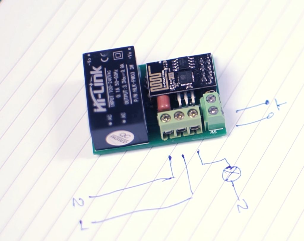
由于图中所示,将模块正确连接到交流电
Line ---》 L
Neutral ---》 N
Light Line‘---》 B
在接线端子SW中添加您喜欢的瞬时按钮。
识别电源线,中性线和轻型电缆:
进行连接并放置按钮,拧紧螺钉并进行测试
如果您是视觉学习者,请查看以下视频教程。您可以找到我精心构建的用于构建此项目的所有步骤:
步骤8:摘要:
在本指南中,我们刚刚学习了如何建立一个可以通过语音,手机应用程序或PC进行Internet控制的WiFi开关,让您控制卧室或其他任何地方的灯泡。该设备基于ESP8266 WiFi模块工作,该模块是一个很小的模块,可让项目轻松上线。而且该设备可用于控制许多不同的设备,例如风扇,电机,窗帘,灯,LED灯条等。
责任编辑:wv
-
PoE交换机与非PoE交换机的比较:两者能否协同工作?2025-03-21 1964
-
[分享]常见网络交换机故障及应用问答2008-06-02 4655
-
接入层交换机、汇聚层交换机和核心层交换机的区别2021-06-04 7925
-
网络交换机2023-04-28 1596
-
交换机简介以及配置文档2017-09-05 883
-
工业控制交换机和工业交换机的区别2020-01-21 2545
-
核心交换机、汇聚交换机与普通交换机的区别介绍2020-03-19 13750
-
家庭交换机怎么安装_交换机网速是平分的吗2020-03-25 11385
-
什么是网络交换机?网络交换机的分类标准2022-08-10 4226
-
交换机的种类以及使用2023-05-05 4594
-
千兆交换机和百兆交换机应该如何选择?2023-06-18 6475
-
PoE交换机可以当普通交换机使用吗2023-06-27 9571
-
核心交换机和普通交换机的区别?2023-12-07 3679
-
管理型交换机 vs. 非管理型交换机2023-12-25 2302
-
汇聚交换机和核心交换机区别2024-01-22 8002
全部0条评论

快来发表一下你的评论吧 !

