
蓝牙低功耗存在检测器的制作教程
电子说
描述
步骤1:零件
我正在使用ESP32 Feather,但其他任何功能都可以使用
1 5v继电器
1 TIP31C转换器
1个BLE服务器设备(任何信标设备)
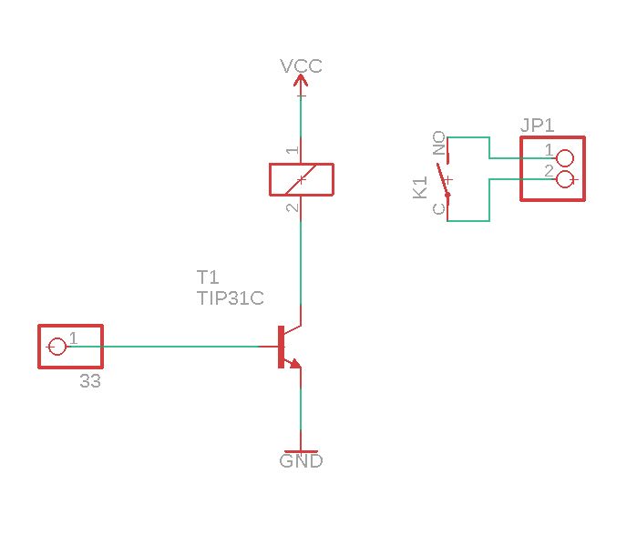
由于ESP32的3V3数字输出电压和电流不足,因此TIP31C用于控制继电器的方式
继电器控制120V灯光,腕带可检测到人的存在。
步骤2:电路

此很简单,ESP32的引脚号33到达晶体管的基极,因此我们可以添加5V VCC信号,并通过3V3电压输出控制更大的电压,然后,通过继电器我们可以控制120V
步骤3:代码
#include “BLEDevice.h”
int Lampara = 33;
int Contador = 0; static BLEAddress *pServerAddress;
BLEScan* pBLEScan;
BLEClient* pClient;
bool deviceFound = false;
bool Encendida = false;
bool BotonOff = false; String knownAddresses[] = { “your:device:mac:address”};
unsigned long entry; static void notifyCallback(
BLERemoteCharacteristic* pBLERemoteCharacteristic,
uint8_t* pData,
size_t length,
bool isNotify) {
Serial.print(“Notify callback for characteristic ”);
Serial.print(pBLERemoteCharacteristic-》getUUID().toString().c_str());
Serial.print(“ of data length ”);
Serial.println(length);
} class MyAdvertisedDeviceCallbacks: public BLEAdvertisedDeviceCallbacks {
void onResult(BLEAdvertisedDevice Device){
//Serial.print(“BLE Advertised Device found: ”);
//Serial.println(Device.toString().c_str());
pServerAddress = new BLEAddress(Device.getAddress());
bool known = false;
bool Master = false;
for (int i = 0; i 《 (sizeof(knownAddresses) / sizeof(knownAddresses[0])); i++) {
if (strcmp(pServerAddress-》toString().c_str(), knownAddresses[i].c_str()) == 0)
known = true;
}
if (known) {
Serial.print(“Device found: ”);
Serial.println(Device.getRSSI());
if (Device.getRSSI() 》 -85) {
deviceFound = true;
}
else {
deviceFound = false;
}
Device.getScan()-》stop();
delay(100);
}
}
}; void setup() {
Serial.begin(115200);
pinMode(Lampara,OUTPUT);
digitalWrite(Lampara,LOW);
BLEDevice::init(“”);
pClient = BLEDevice::createClient();
pBLEScan = BLEDevice::getScan();
pBLEScan-》setAdvertisedDeviceCallbacks(new MyAdvertisedDeviceCallbacks());
pBLEScan-》setActiveScan(true);
Serial.println(“Done”);
} void Bluetooth() {
Serial.println();
Serial.println(“BLE Scan restarted.。..。”);
deviceFound = false;
BLEScanResults scanResults = pBLEScan-》start(5);
if (deviceFound) {
Serial.println(“Encender Lamara”);
Encendida = true;
digitalWrite(Lampara,HIGH);
Contador = 0;
delay(10000);
}
else{
digitalWrite(Lampara,LOW);
delay(1000);
}
} void loop() {
Bluetooth();
}
步骤4:用于灯光控制的PCB
我在原型PCB上制作了这个电路,以使事情变得更干净。
第5步:完成
然后您完成了!
您可以使用此代码打开门,或控制其他事情
责任编辑:wv
-
蓝牙低功耗技术2011-05-13 3521
-
低功耗蓝牙怎么低功耗?如何界定2018-02-06 3728
-
超低功耗无线PIR运动检测器设计包括BOM及层图2018-10-16 2387
-
Sub-1 GHz无线运动检测器系统2019-03-27 1958
-
反射式红外检测器电路及制作2009-04-14 1535
-
车位检测器低功耗测试方案2016-12-21 1646
-
车辆检测器的低功耗设计2017-09-05 1123
-
ADM8641/ADM8642超低功耗电压检测器数据表2021-04-17 712
-
UG-1777:评估ADM8641/ADM8642超低功耗电压检测器2021-04-28 674
-
如何利用ESP32和Arduino制作BLE检测器2022-08-09 9106
-
射频功率检测器制作方案2022-10-19 1104
-
低功耗蓝牙漏水检测器开源分享2023-02-02 594
-
低功耗多功能电压检测器XC6138系列简述2023-07-25 1498
-
双通道、低功耗、高精度电压检测器TPS37xx 数据表2024-03-14 455
-
基于STEVAL-BLUEPIRV1的蓝牙低功耗运动检测技术解析2025-10-30 353
全部0条评论

快来发表一下你的评论吧 !

