

如何将1个或多个Arduino与树莓派结合使用
电子说
描述
步骤1:RaspberryPi电路
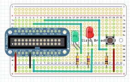
您将需要一种将RaspberryPi线路连接到面包板的方法。您可以使用公/母跳线,但是本页上列出的Adafruit的Pi补鞋匠将使其变得更容易:http://www.adafruit.com/search?q=cobbler
对于您还将需要的RaspberryP电路:
RaspberryPi
面包板
跳线
2-LED,我用了一个红色和绿色。
2-330-560欧姆电阻,用于LED。
1-按钮开关
1-10K电阻,下拉电阻用于开关。
使用这些部件复制上图中的电路。
除了http://www.adafruit上Adafruit的电阻器外,您还可以获取所需的一切。 .com/
或在Sparkfun上https://www.sparkfun.com/
Sparkfun还提供了一个不错的电阻器组合,其中包括您需要的每个电阻值中的25个,您可以在这里https://www.sparkfun.com/products/10969。
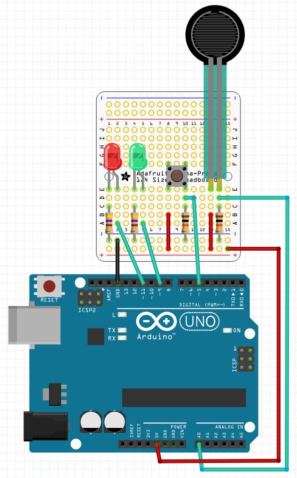
第2步:Arduino电路
第一个Arduino使用了从RaspberryPi调用的pinMode(),digitalRead(),digitalWrite(),analogRead()和pwmWrite()函数。这是我知道将最简单的方法添加到RaspberryPi的模数转换器。请注意,connectionPi使用pwmWrite而不是AnalogWrite,它更准确。
第二个Arduino只是在RaspberryPi的控制下,闪烁了13针上的内置LED。这只是表明它确实可以控制多个Arduino。它还显示了connectionPi的多线程功能的很好但简单的使用。
如果只有一个Arduino,您仍然可以尝试该程序,第5步是使用一个arduino的程序。
我在原型屏蔽板上构建了Arduino电路,但我展示了
对于Arduino电路,您将需要:
2-Arduinos
2-连接到的USB电缆RaspberryPi
面包板
跳线
2-LED,我使用了一个红色和一个绿色。
2-330-560欧姆电阻,用于LED。
1-按钮开关
1-电阻传感器
2-10K电阻,开关和传感器的下拉电阻。
使用这些部件复制上图中的电路。
我在电阻传感器中使用了力敏电阻,但是光电管或弯曲传感器也能正常工作。您也可以使用电位计。要为电位器接线,请忘掉10K电阻,将中间引线连接到该引脚,一端引线连接到正极轨,另一端接地。
步骤3:代码
为您的RaspberryPi下载此程序。
使用以下命令对其进行编译:
gcc -o DRCtest DRCtest.c -lwiringPi -lpthread
并使用以下命令运行它:
sudo 。/DRCtest
/************************************************************************
* DRCtest.c - Test program for Drogon Remote Control. (DRC)
*
* On the first Arduino:
* LEDs are connected to pins nine and eleven, with 560 Ohm current limiting resistors.
* A push button switch is connected to pin five, with a 10K pull-down resistor.
* A resistive sensor is connected to analog pin zero, with a 10K pull-down resistor.
* The only connection to the RaspberryPi is the USB cable.
* The program in the RaspberryPi is controling the Arduino.
* The DRC.ino program must be installed and running.
*
* Nothing is connected to the second Arduino.
*
* On the RaspberryPi:
* LEDs are connected to pins nine and eleven, with 560 Ohm current limiting resistors.
* A push button switch is connected to pin five, with a 10K pull-down resistor.
* The pin numbers for the RaspberryPi use the wiringPi pin numbering scheme.
*
* The loop() function does a digitalRead of the push button on the Arduino
* and digitalWrites the value to the both red LEDs
* Next it performs an analogRead of the force sensitive resistor, divides
* the value by four, and pwmWrites the value to both green LEDs.
* Then is does a digitalRead of the push button on the RaspberryPi
* and digitalWrites the value to the both red LEDs
*
************************************************************************/#include
#include
#include
#define BASE 100
#define BASE2 200/*****************************************************************************
* The second thread blinks the built in LED on pin 13 of the Second Arduino.
* The code here runs concurrently with the main program in an infinite loop.
*****************************************************************************/
PI_THREAD(arduino2)
{
for(;;)
{
digitalWrite(BASE2+13, HIGH); // Turn pin 13 on.
delay(500);
digitalWrite(BASE2+13, LOW); // Turn pin 13 off.
delay(500);
}
}/**************************************************************************
* setup() function
**************************************************************************/
void setup(void)
{
wiringPiSetup();
drcSetupSerial(BASE, 20, “/dev/ttyACM0”, 115200);
drcSetupSerial(BASE2, 20, “/dev/ttyACM1”, 115200);
int x = piThreadCreate(arduino2); // Start second thread.
if (x != 0) printf(“It didn‘t start. ”);
// Pins on Arduino:
pinMode (BASE+11, PWM_OUTPUT); // Reset pin to maximum value
pwmWrite(BASE+11, 255); // after PWM write.
pinMode (BASE+5, INPUT); // Pin 5 used for digitalRead.
pinMode (BASE+9, PWM_OUTPUT); // Pin 9 used for pwmWrite.
// Pin A0 is used for analogRead.
// Pins on second Arduino:
pinMode (BASE2+13, OUTPUT); // Pin 13 used for digitalWrite.
// Pins on RaspberryPi:
pinMode(0, OUTPUT); // Pin 0 used for digitalWrite.
pinMode(5, INPUT); // Pin 5 used for digitalRead.
pinMode(1, PWM_OUTPUT); // Pin 1 used for pwmWrite.
}/**************************************************************************
* loop() function
**************************************************************************/
void loop(void)
{
digitalWrite(BASE+11, digitalRead(BASE+5)); // If Arduino button is pressed
digitalWrite(0, digitalRead(BASE+5)); // turn on both red LEDs.
pwmWrite(BASE+9, (analogRead(BASE)/4)); // Varies the brightness of both green
pwmWrite(1, (analogRead(BASE)/4)); // LEDs according to pressure applied
// to the force sensitive resistor.
digitalWrite(BASE+11, digitalRead(5)); // If RaspberryPi button is pressed
digitalWrite(0, digitalRead(5)); // turn on both red LEDs.
}/**************************************************************************
* main() function
**************************************************************************/
int main (void)
{
setup();
for(;;)
{
loop();
}
return 0 ;
}
第4步:将它们放在一起
将第6步中的Arduino草图上传到您将要使用的Arduino。
关闭RaspberryPi并连接RaspberryPi电路。插入USB端口之前必须先关闭RaspberryPi,否则RaspberryPi不会将它们注册为正确的设备。第一个Arduino是/dev/ttyACM0,第二个是/dev/ttyACM1。如果您没有将Arduinos插入正确的USB端口,则会将命令发送到错误的Arduino。在B +型上,第一个Arduino在与GPIO接头相同的顶部USB端口中。第二个Arduino在下面的底部USB端口中。如果您使用的是USB集线器,则必须在各个端口之间切换以查看其工作原理。
打开RaspberryPi并使用以下命令运行该程序:
sudo 。/DRCtest
按下RaspberryPi电路上的按钮应点亮红色LED。 RaspberryPi电路和第一个Arduino。
按下第一个Arduino上的按钮也会点亮两个红色LED。
改变电阻传感器会导致绿色LED的亮度发生变化。
在第二个Arduino上,板载引脚13指示器LED应当闪烁并熄灭。
如果第一次不起作用,请关闭所有设备并反转USB端口。
步骤5:使用一个Arduino运行程序
如果没有第二个Arduino,您仍然可以尝试演示。
下载此版本的程序并使用以下命令进行编译:
gcc- o DRCtest-1 DRCtest-1.c -lwiringPi
并使用以下命令运行程序:
sudo 。/DRCtest-1
仅使用一个Arduino您可以在关闭电源的情况下将Arduino插入任何USB端口,然后它将正常工作。
责任编辑:wv
-
树莓派“吉尼斯世界记录”:将树莓派的性能发挥到极致的项目!2025-05-22 1924
-
树莓派与Arduino的区别是什么2024-11-11 4212
-
如何将红外接收器或TSOP与Arduino结合使用2023-02-01 817
-
如何将RTC DS1与Arduino结合使用来进行提醒2023-01-03 1073
-
如何将柔性传感器与树莓派连接并在LCD屏幕上显示其值2022-12-31 5668
-
如何将WizFi360 EVB Mini添加到树莓派Pico Python2022-12-01 834
-
如何将一个树莓派官方原始系统镜像移植到paipai one设备2021-12-16 1278
-
使用Arduino和树莓派实现门禁系统设计的资料说明2021-03-17 1171
-
如何使树莓派与Arduino蓝牙通信?2020-06-05 2682
-
如何将树莓派网关连接到TTN——手把手教你如何将树莓派网关连接到服务器之第四篇2020-04-17 2026
-
如何将树莓派网关与外网连接——手把手教你如何将树莓派网关连接到服务器之第三篇2020-04-16 3107
-
arduino和树莓派的区别2017-11-08 26648
-
求教:树莓派和arduino的通信2015-09-23 18259
-
如何将树莓派变成一个FM的音频发射器2014-07-01 20110
全部0条评论

快来发表一下你的评论吧 !
