
SPI接口的工作原理
IC应用电路图
描述
MAX7456随屏显示(OSD)发生器具有SPI™兼容接口,本应用笔记介绍了SPI接口的工作原理,文中还包含在微控制器内逐位模拟SPI接口的控制器C程序。
MAX7456串行接口
MAX7456单通道单色随屏显示(OSD)发生器预装了256个字符和图形,并可通过SPI接口在线编程。通过SPI兼容串行接口可以设置工作模式、显示存储器以及字符存储器。状态(STAT)寄存器、显示存储器数据输出(DMDO)寄存器和字符存储器数据输出(CMDO)寄存器都可读,可以对其进行写操作和读操作。关于MAX7456寄存器及存储器结构的详细信息请参考数据资料和应用笔记4117,"使用MAX7456存储器和评估板文件生成定制字符和图形"。
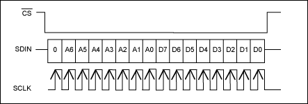
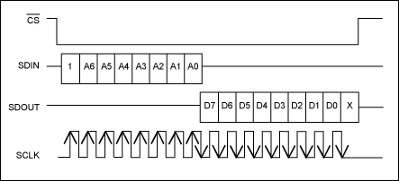
MAX7456支持高达10MHz接口时钟(SCLK)。图1为写数据时序,图2是从器件读数据的时序。
写寄存器时,拉低/CS可使能串行接口。在SCLK的上升沿从SDIN读取数据。当/CS变为高电平时,数据锁存到输入寄存器。如果传输过程中/CS变高,程序终止(即数据不写入寄存器)。/CS变低之后,器件等待从SDIN读入第一个字节,以确定正在执行的数据传输类型。
读寄存器时,如上文所述,拉低/CS。地址在SCLK的上升沿锁入SDIN。然后数据在SCLK的下降沿从SDOUT输出。
SPI命令长度为16位:最高8位(MSB)代表寄存器地址,最低8位(LSB)代表数据(图1和2)。这种格式有两个例外:
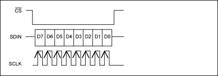
- 自动递增写模式,用于访问显示存储器,是一个8位操作(图3)。写数据前必须写入起始地址。对显示存储器执行自动递增写命令时,8位地址由内部产生,串口只需8位数据,如图3所示。
- 从显示存储器读字符数据时,若处于16位工作模式,应该是24位(8位地址+16位数据)。
执行读操作时,只需要8位地址,如图2所示。
图1. 写操作
图2. 读操作
图3. 自动递增写操作
C程序
下文给出的C程序已针对MAXQ2000微控制器进行了编译,用于MAX7456评估(EV)板。本文给出了完整的程序例程。程序是自述文档,几乎没有附加说明。C程序可从以下文件获得:spi.c和MAX7456.h。
以下程序使用了SPI协议的标准定义,MAXQ2000处理器为SPI主机,MAX7456是SPI从器件。
CS与MAX7456数据资料中的定义相同。
SDIN对应于MOSI (主机出从器件入)。
SDOUT对应于MOSI (主机入从器件出)。
SCLK对应于CK。
前缀SPI_用于全部程序。
数据结构
下文所示数据结构可直接或逐位读写数据,用于独立访问SPI端口。
/* Port 5 Output Register */
__no_init volatile __io union
{
  unsigned char PO5;
  struct
  {
    unsigned char bit0          : 1;
    unsigned char bit1          : 1;
    unsigned char bit2          : 1;
    unsigned char bit3          : 1;
    unsigned char bit4          : 1;
    unsigned char bit5          : 1;
    unsigned char bit6          : 1;
    unsigned char bit7          : 1;
  } PO5_bit;
}
上述代码将一个单字节赋值给PO5,这是微控制器输出端口的地址。然后将另一个字节赋值给相同的可以逐位访问的存储器地址。
因此,可用以下命令直接对该端口进行寻址:
PO5 = 0x10;
或用以下命令逐位读写:
PO5_bit.bit4 = 1;
如果该程序用于其它处理器,该结构需要重新编写。
如果采用不支持位字段宽度的老式C编译器,可用位布尔运算设置及清除位:
/* Portable bit-set and bit-clear macros. */
#define BIT_SET(sfr,bitmask) sfr |= (bitmask)
#define BIT_CLR(sfr,bitmask) sfr &=~ (bitmask)
#define BIT0 0x01
#define BIT1 0x02
#define BIT2 0x04
#define BIT3 0x08
#define BIT4 0x10
#define BIT5 0x20
#define BIT6 0x40
#define BIT7 0x80
example: BIT_SET(PO5,BIT0); BIT_CLR(PO5,BIT6);
宏
以下是一个简单的编程技巧,使程序更容易移植:用宏定义控制器引脚排列,如下所示。
#define SPI_CS         PO5_bit.bit4                            // PO5_bit.bit4 = active-low CS—chip select
#define SPI_MOSI       PO5_bit.bit5                            // PO5_bit.bit5 = MOSI—master out slave in,
                                                               // data to MAX7456
#define SPI_MISO       PI5_bit.bit7                            // PO5_bit.bit7 = MISO—master in slave out,
                                                               // data from MAX7456
#define SPI_CK         PO5_bit.bit6                            // PO5_bit.bit6 = SCK - SPI clock
用以上宏和数据结构可以单独置位及复位每个IO口,命令如下:
SPI_CS = 1;
改变宏时相应引脚也将改变,将上述代码用于其它设计时,如果SPI口引脚排列不同,或为了实现更理想的PCB布局而对引脚进行重新排列,上述程序非常有用。
单字节写操作程序
单字节写操作(图1)程序如下所示。如果可以保证在程序入口处的/CS和CK线状态正确,可以去掉前两条命令。
程序首先发送地址,然后发送数据。进行两次循环。采用单循环及16位数据存储可以简化程序。在MAXQ2000微控制器中执行16位“int”所占用的时间比执行8位“char”长,因此需进行权衡考虑。
/*********************************************
 * spiWriteReg
 *
 * Writes to an 8-bit register with the SPI port
 ************************************************************/

void spiWriteReg(const unsigned char regAddr, const unsigned char regData)
{

  unsigned char SPICount;                                       // Counter used to clock out the data

  unsigned char SPIData;                                        // Define a data structure for the SPI data

  SPI_CS = 1;                                        		// Make sure we start with active-low CS high
  SPI_CK = 0;                                        		// and CK low

  SPIData = regAddr;                                            // Preload the data to be sent with Address
  SPI_CS = 0;                                                   // Set active-low CS low to start the SPI cycle
                                                                // Although SPIData could be implemented as an "int",
                                                                // resulting in one
                                                                // loop, the routines run faster when two loops
                                                                // are implemented with
                                                                // SPIData implemented as two "char"s.

  for (SPICount = 0; SPICount < 8; SPICount++)                  // Prepare to clock out the Address byte
  {
    if (SPIData & 0x80)                                         // Check for a 1
      SPI_MOSI = 1;                                             // and set the MOSI line appropriately
    else
      SPI_MOSI = 0;
    SPI_CK = 1;                                                 // Toggle the clock line
    SPI_CK = 0;
    SPIData <<= 1;                                              // Rotate to get the next bit
  }                                                             // and loop back to send the next bit

                                                                // Repeat for the Data byte
  SPIData = regData;                                            // Preload the data to be sent with Data
  for (SPICount = 0; SPICount < 8; SPICount++)
  {
    if (SPIData & 0x80)
      SPI_MOSI = 1;
    else
      SPI_MOSI = 0;
    SPI_CK = 1;
    SPI_CK = 0;
    SPIData <<= 1;
  }
  SPI_CS = 1;
  SPI_MOSI = 0;
}
读字节操作程序
读字节操作(图2)程序如下所示,与上述程序类似。首先发送地址,然后发送时钟从MISO读回数据。
/*********************************************
 * spiReadReg
 *
 * Reads an 8-bit register with the SPI port.
 * Data is returned.
 *******************************************************/

unsigned char spiReadReg (const unsigned char regAddr)
{

  unsigned char SPICount;                                       // Counter used to clock out the data

  unsigned char SPIData;

  SPI_CS = 1;                                                   // Make sure we start with active-low CS high
  SPI_CK = 0;                                                   // and CK low
  SPIData = regAddr;                                            // Preload the data to be sent with Address and Data

  SPI_CS = 0;                                                   // Set active-low CS low to start the SPI cycle
  for (SPICount = 0; SPICount < 8; SPICount++)                  // Prepare to clock out the Address and Data
  {
    if (SPIData & 0x80)
      SPI_MOSI = 1;
    else
      SPI_MOSI = 0;
    SPI_CK = 1;
    SPI_CK = 0;
    SPIData <<= 1;
  }                                                             // and loop back to send the next bit
  SPI_MOSI = 0;                                                 // Reset the MOSI data line

  SPIData = 0;
  for (SPICount = 0; SPICount < 8; SPICount++)                  // Prepare to clock in the data to be read
  {
    SPIData <<=1;                                               // Rotate the data
    SPI_CK = 1;                                                 // Raise the clock to clock the data out of the MAX7456
    SPIData += SPI_MISO;                                        // Read the data bit
    SPI_CK = 0;                                                 // Drop the clock ready for the next bit
  }                                                             // and loop back
  SPI_CS = 1;                                                   // Raise CS

  return ((unsigned char)SPIData);                              // Finally return the read data
}
自动递增模式下的写字节操作程序
自动递增模式下的写字节操作(图3)程序如下所示,与和上述单字节写程序类似。首先发送地址,然后发送时钟从MISO读回数据。
/***********************************************
 * spiWriteRegAutoIncr
 *
 * Writes to an 8-bit register with the SPI port using the MAX7456's autoincrement mode
 *************************************************/

void spiWriteRegAutoIncr(const unsigned char regData)
{
  unsigned char SPICount;                                       // Counter used to clock out the data

  unsigned char SPIData;                                        // Define a data structure for the SPI data.

  SPI_CS = 1;                                                   // Make sure we start with active-low CS high
  SPI_CK = 0;                                                   // and CK low
  SPIData = regData;                                            // Preload the data to be sent with Address and Data

  SPI_CS = 0;                                                   // Set active-low CS low to start the SPI cycle
  for (SPICount = 0; SPICount < 8; SPICount++)                  // Prepare to clock out the Address and Data
  {
    if (SPIData & 0x80)
      SPI_MOSI = 1;
    else
      SPI_MOSI = 0;
    SPI_CK = 1;
    SPI_CK = 0;
    SPIData <<= 1;
  }                                                             // and loop back to send the next bit
  SPI_MOSI = 0;                                                 // Reset the MOSI data line
}
自动递增模式下写显示存储器的程序
自动递增模式下写显示存储器的程序如下,程序使用称为 "data"的全局变量数组。定义如下:
extern volatile unsigned char data[DATA_BUF_LENGTH];

DATA_BUF_LENGTH = 968
调用程序时,data[]包含显示存储器内容,格式如下:
data[0] = ignored (contains a command byte used by the EV kit GUI software)
data[1] = character byte 1
data[2] = attribute byte 1
data[3] = character byte 2
data[4] = attribute byte 2
etc.
自动递增模式通过写0xFF结束,所以该模式下不能向显示寄存器写0xFF。如果需要写OxFF,可以采用单字节写指令。
/*************************************************
 * spiWriteCM
 *
 * Writes to the Display Memory (960 bytes) from "data" extern.
 * 960 = 16 rows × 30 columns × 2 planes {char vs. attr} screen-position-indexed memory
 *****************************************************/

void spiWriteCM()                                               // On entry: global data[1..960]
                                                                // contains char+attr bytes
                                                                // (optionally terminated by 0xFF data)
                                                                // First, write data[1,3,5,...] Character plane;
                                                                // MAX7456 WriteReg(0x05,0x41)
                                                                // "Character Memory Address High";
                                                                // 0x02:Attribute bytes;
                                                                // 0x01:character memory address msb
{
   volatile unsigned int Index = 0x0001;                        // Index for lookup into
                                                                // data[1..960]
   spiWriteReg(DM_ADDRH_WRITE,0x00);                            // initialise the Display Memory high-byte
   spiWriteReg(DM_ADDRL_WRITE,0x00);                            // and the low-byte
   spiWriteReg(DM_MODE_WRITE ,0x41);                            // MAX7456 WriteReg(0x04,0x41) "Display Memory Mode";
                                                                // 0x40:Perform 8-bit operation; 0x01:AutoIncrement

   Do                                                           // Loop to write the character data
   {
      if (data[Index] == 0xFF) {                                // Check for the break character
           break; }                                             // and finish if found
      spiWriteRegAutoIncr(data[Index]);                         // Write the character
      Index += 2;                                               // Increment the index to the next character,
                                                                // skipping over the attribute
   } while(Index < 0x03C1);                                     // 0x03C1 = 961
                                                                // and loop back to send the next character

   spiWriteRegAutoIncr(0xFF);                                   // Write the "escape character" to end AutoIncrement
                                                                // mode

   spiWriteReg(DM_ADDRH_WRITE,0x02);                            // Second, write data[2,4,6,...]
                                                                // Attribute plane; MAX7456
                                                                // WriteReg(0x05,0x41)
                                                                // "Character Memory Address High";
                                                                // 0x02:Attribute bytes; 0x01:character memory address
                                                                // msb

   spiWriteReg(DM_ADDRL_WRITE,0x00);
   spiWriteReg(DM_MODE_WRITE,0x41);                             // MAX7456 WriteReg(0x04,0x41) "Character Memory
                                                                // Mode"; 0x40:Perform 8-bit operation; 0x01:Auto-
                                                                // Increment

   Index = 0x0002;
   do
   {
      if (data[Index] == 0xFF)
         break;
      spiWriteRegAutoIncr(data[Index]);
      Index += 2;
   } while(Index < 0x03C1);
   spiWriteRegAutoIncr(0xFF);
}
写字符存储器程序
向字符存储器写一个字符的程序如下,每个字符占用18行,每行12像素,共216像素。由于每个字节定义4个像素,因此定义每一个字符需要54字节。字符数据位于程序入口处的data[] (与上述写显示存储器的程序类似)。
写字符存储器时需要进行一些附加说明,存储器为非易失,因此,写存储器大约需要12ms,由MAX7456执行。只有完整的54字节字符才可以写入字符存储器。
该器件包含一个54字节映射存储器。首先把需要写入的字符数据写入映射存储器,然后器件将该数据装载到NVM字符存储器。
用来写字符存储器的寄存器有以下几种:
- 字符存储器模式 = 0x08。向寄存器写0xA0,使器件把映射存储器的内容装载到NVM字符存储器。
- 字符存储器地址高位 = 0x09。包括了即将写入字符的地址。
- 字符存储器地址低位 = 0x0A。
- 字符存储器数据输入 = 0x0B。
- Status = 0xA0,读取该寄存器以决定何时可以写入字符存储器。
在程序入口处,data[1]包括即将写入字符的地址,data[2...54]包括字符数据。
向NVM字符存储器写字符时,首先写字符地址。然后将每个字节写入映射存储器。写映射存储器时没有自动递增模式,所以每次写操作必须写入映射存储器地址。向字符存储器模式寄存器写0xA0,可以把映射存储器的内容装载到NVM字符存储器。然后器件将状态寄存器第5位置高,表明不能写入字符存储器。完成后,器件将该位复位至低。数据从映射存储器移向字符存储器时不能写映射存储器。
为了避免出现显示器闪烁,在写字符存储器之前程序禁止了OSD。
/****************************************
 * spiWriteFM
 *
 * Writes to the Character Memory (54 bytes) from "data" extern
******************************************/
void spiWriteFM()
{
     unsigned char Index;

     spiWriteReg(VIDEO_MODE_0_WRITE,spiReadReg
                 (VIDEO_MODE_0_READ) & 0xF7);                   // Clear bit 0x08 to DISABLE the OSD display
     spiWriteReg(FM_ADDRH_WRITE,data[1]);                       // Write the address of the character to be written
                                                                // MAX7456 glyph tile definition
                                                                // length = 0x36 = 54 bytes
                                                                // MAX7456 64-byte Shadow RAM accessed
                                                                // through  FM_DATA_.. FM_ADDR.. contains a single
                                                                // character/glyph-tile shape
     for(Index = 0x00; Index < 0x36; Index++)
     {
          spiWriteReg(FM_ADDRL_WRITE,Index);                    // Write the address within the shadow RAM
          spiWriteReg(FM_DATA_IN_WRITE,data[Index + 2]);        // Write the data to the shadow RAM
     }

     spiWriteReg(FM_MODE_WRITE, 0xA0);                          // MAX7456 "Font Memory Mode" write 0xA0 triggers
                                                                // copy from 64-byte Shadow RAM to NV array.

     while ((spiReadReg(STATUS_READ) & 0x20) != 0x00);          // Wait while NV Memory status is BUSY
                                                                // MAX7456 0xA0 status bit 0x20: NV Memory Status
                                                                // Busy/~Ready
}
MAX7456头文件
下面列出了MAX7456的头文件,以下代码决定了器件的寄存器映射。
/**********************************************
 * spiWriteRegAutoIncr
 *
 * Writes to an 8-bit register with the SPI port by using the MAX7456's autoincrement mode
 *******************************************/
                                                                // MAX7456 VIDEO_MODE_0 register
#define VIDEO_MODE_0_WRITE              0x00
#define VIDEO_MODE_0_READ               0x80
#define VIDEO_MODE_0_40_PAL             0x40
#define VIDEO_MODE_0_20_NoAutoSync      0x20
#define VIDEO_MODE_0_10_SyncInt         0x10
#define VIDEO_MODE_0_08_EnOSD           0x08
#define VIDEO_MODE_0_04_UpdateVsync     0x04
#define VIDEO_MODE_0_02_Reset           0x02
#define VIDEO_MODE_0_01_EnVideo         0x01
                                                                // VIDEO MODE 0 bitmap
#define NTSC                            0x00
#define PAL                             0x40
#define AUTO_SYNC                       0x00
#define EXT_SYNC                        0x20
#define INT_SYNC                        0x30
#define OSD_EN                          0x08
#define VERT_SYNC_IMM                   0x00
#define VERT_SYNC_VSYNC                 0x04
#define SW_RESET                        0x02
#define BUF_EN                          0x00
#define BUF_DI                          0x01

                                                                // MAX7456 VIDEO_MODE_1 register
#define VIDEO_MODE_1_WRITE              0x01
#define VIDEO_MODE_1_READ               0x81

                                                                // MAX7456 DM_MODE register
#define DM_MODE_WRITE                   0x04
#define DM_MODE_READ                    0x84

                                                                // MAX7456 DM_ADDRH register
#define DM_ADDRH_WRITE                  0x05
#define DM_ADDRH_READ                   0x85

                                                                // MAX7456 DM_ADDRL register
#define DM_ADDRL_WRITE                  0x06
#define DM_ADDRL_READ                   0x87

                                                                // MAX7456 DM_CODE_IN register
#define DM_CODE_IN_WRITE                0x07
#define DM_CODE_IN_READ                 0x87

                                                                // MAX7456 DM_CODE_OUT register
#define DM_CODE_OUT_READ                0xB0

                                                                // MAX7456 FM_MODE register
#define FM_MODE_WRITE                   0x08
#define FM_MODE_READ                    0x88

                                                                // MAX7456 FM_ADDRH register
#define FM_ADDRH_WRITE                  0x09
#define FM_ADDRH_READ                   0x89

                                                                // MAX7456 FM_ADDRL register
#define FM_ADDRL_WRITE                  0x0A
#define FM_ADDRL_READ                   0x8A

                                                                // MAX7456 FM_DATA_IN register
#define FM_DATA_IN_WRITE                0x0B
#define FM_DATA_IN_READ                 0x8B

                                                                // MAX7456 FM_DATA_OUT register
#define FM_DATA_OUT_READ                0xC0

                                                                // MAX7456 STATUS register
#define STATUS_READ                     0xA0
#define STATUS_40_RESET_BUSY            0x40
#define STATUS_20_NVRAM_BUSY            0x20
#define STATUS_04_LOSS_OF_SYNC          0x04
#define STATUS_02_PAL_DETECTED          0x02
#define STATUS_01_NTSC_DETECTED         0x01

                                              // MAX7456 requires clearing OSD Black Level
                                                // register bit 0x10 after reset
#define OSDBL_WR                        0x6C
#define OSDBL_RD                        0xEC
#define OSDBL_10_DisableAutoBlackLevel  0x10
结论和性能
MAX7456评估板采用工作在20MHz时钟的MAXQ2000微控制器,该微控制器包含内部硬件SPI控制器。因此,MAX7456的SPI端口可以全速工作。上述软件SPI程序工作速度低于硬件控制器。不过针对客户缺少硬件SPI端口的工作环境,程序已优化至最简。
SPI是Motorola, Inc.的商标。
-
SPI(串行外设接口)工作原理介绍2021-03-29 877
-
学习常用接口总线的工作原理2021-08-23 1217
-
SPI接口原理2021-12-07 1085
-
SPI接口的配置步骤有哪些呢2021-12-08 2021
-
SPI是什么?SPI接口有哪些优缺点2021-12-17 1858
-
ADC的工作原理与选型2022-01-13 1456
-
用于MAX7456随屏显示器SPI2009-02-23 1173
-
基于FPGA的串行外围接口SPI设计与实现2012-05-23 9287
-
SPI总线及I2C总线工作原理2015-12-08 1393
-
SPI的工作原理讲解2016-11-11 1536
-
USB接口工作原理_USB接口优点2020-06-10 9970
-
SPI接口应用框图_SPI接口工作模式2020-09-02 4729
-
SPI接口的基本概念和工作原理2023-09-26 5744
-
stm32 HAL库spi接收的同时为什么有数据发送出去?2023-10-26 3145
-
串行接口的工作原理和结构2024-08-25 3900
全部0条评论

快来发表一下你的评论吧 !

